Iron Pre - iron good sound?
built through Frank Wilker
This project description will continue to be supplemented!
last change: 21.03.2024

- design by Zen Mod
- on diyAudio
- posted at 20th June 2016
First meeting
My Muses volume control and input modules have been used in many existing or planned preamplifiers. I have adapted solutions and customized programming for several projects. This is probably more due to the high-quality signal processing of the Muses chip, than to the design of my special hardware and software solutions.
My first contact with the Iron Pre was though Kevin. He asked if it would be possible to integrate my existing PreAmp module into his Iron Pre.
Since the Muses chip can almost always be used where a volume control is required, I answered in the affirmative across the board. As always, special requests came up in the ensuing conversation, such as incorporating the existing input switching relays. Additional output sockets were also requested. Since my solutions are often tailored specifically to the user, I promised him a solution.
Interestingly, during our conversation, there were other inquiries within a few days. This prompted me to take a closer look preamplifier. During my research I first got in contact with Patrick. I call him "the good soul", who made my life (information search) so much easier, that everything seemed to run by itself. It was also him who put me in direct contact with the creator, Zen Mod.
Circuit diagram/explanations
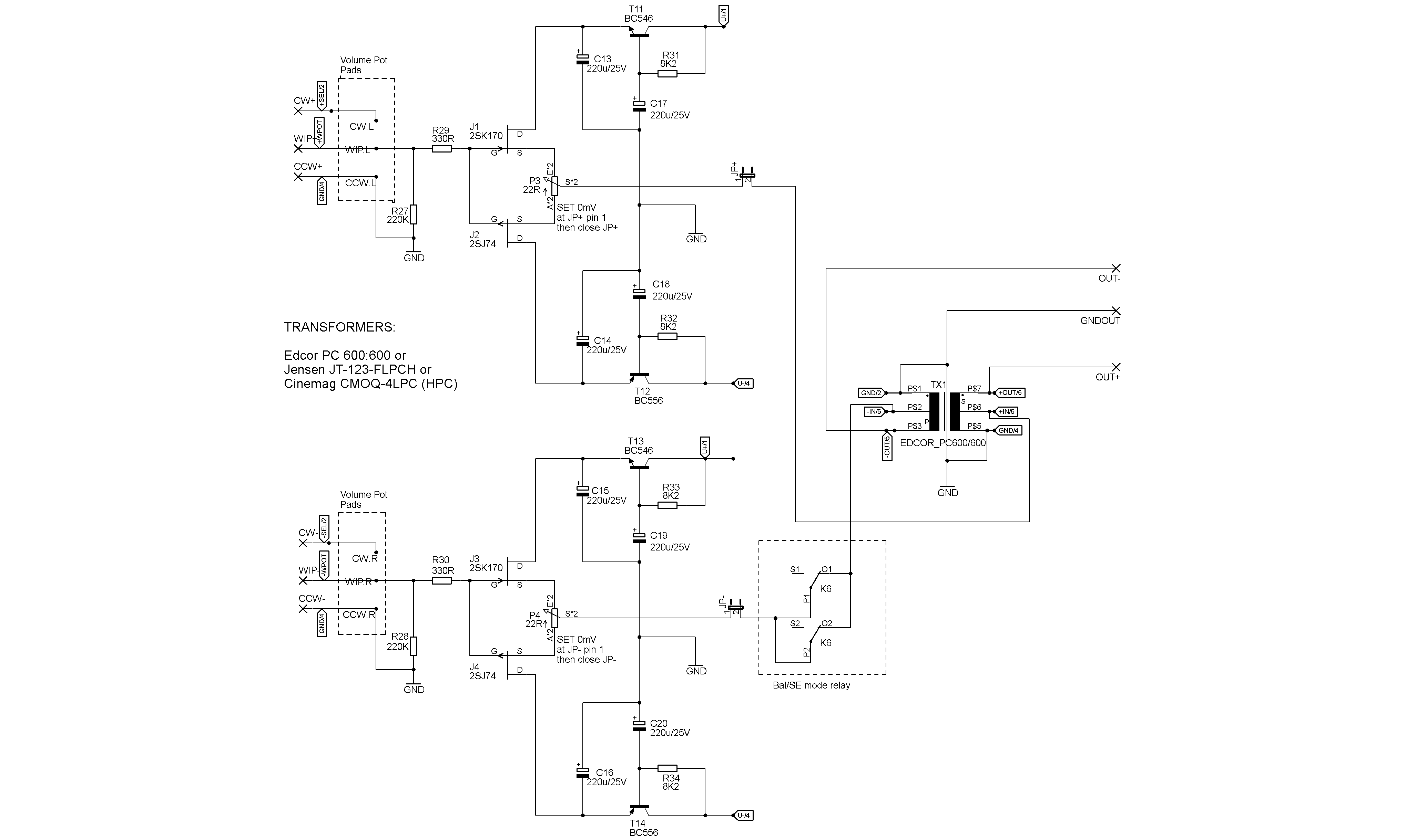
A look at the Iron-Pre schematics immediately showed me the high potential of the design. A complementary pair of JFETs form a Diamond buffer terminated by a transformer. Wow, clean and simple.
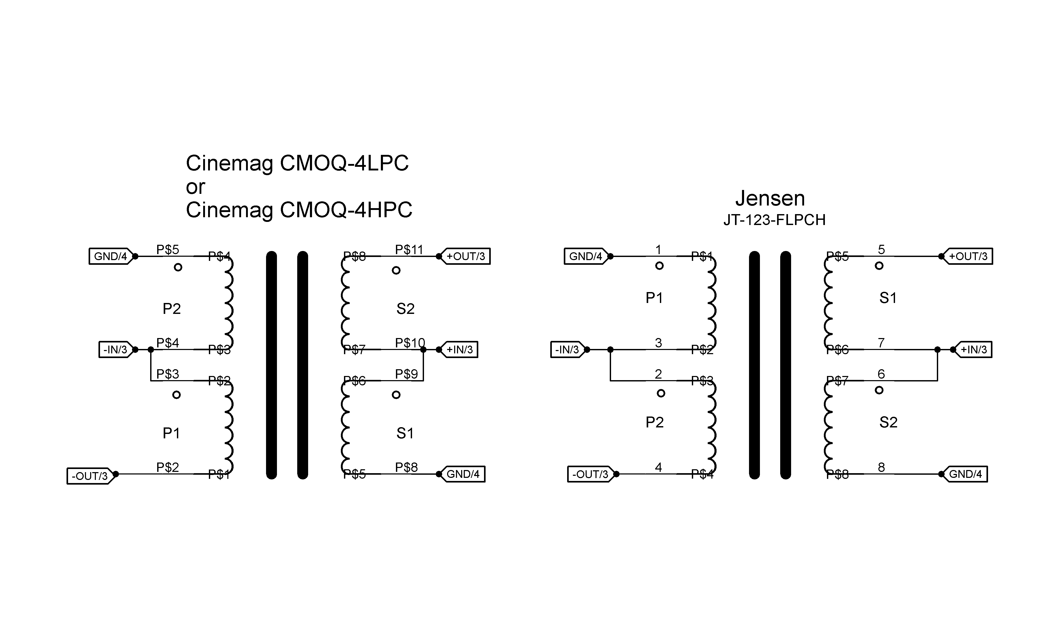
A high-quality onboard power supply (rectification and voltage regulation) along with relay-controlled input switching for 5 inputs are also included. The boards support the use of 600:600 transformers from CineMag, Jensen, and Edcor. Kits purchased from the diyAudio store are supplied with the CineMag CMOQ-4HP transformers preferred by Zen Mod.
In a standard application, the relays are actuated by a rotary switch. A circuit board for connecting the input switch and LED indication of the input selected is included with all Iron Pre kits. The input switching board is connected to the main PCBs via a 14-pin connector. This way the signal remains where it belongs and is not routed through cables and switches before it reaches the circuit for the first time. How poetically written :)
circuit Iron Pre
balanced version
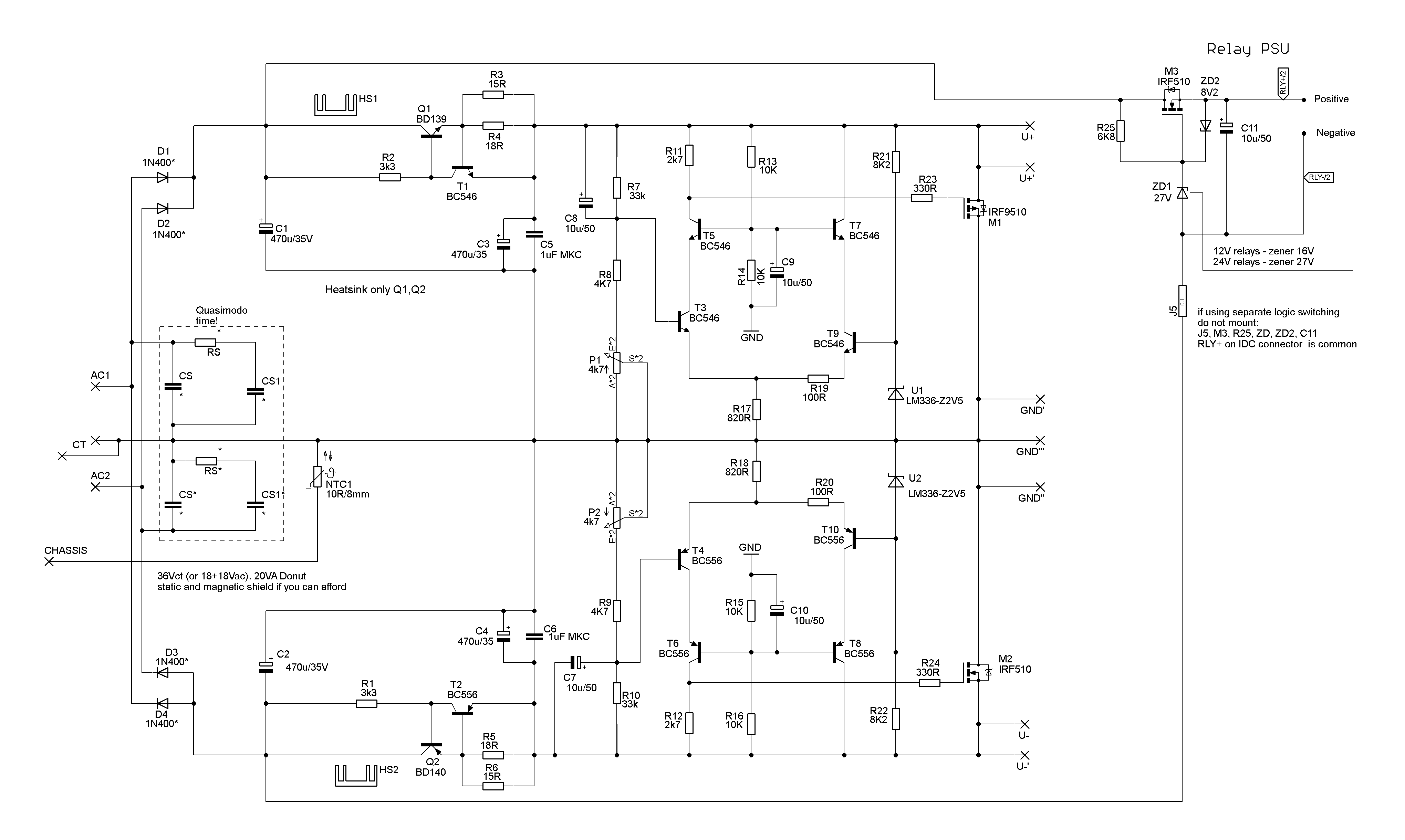
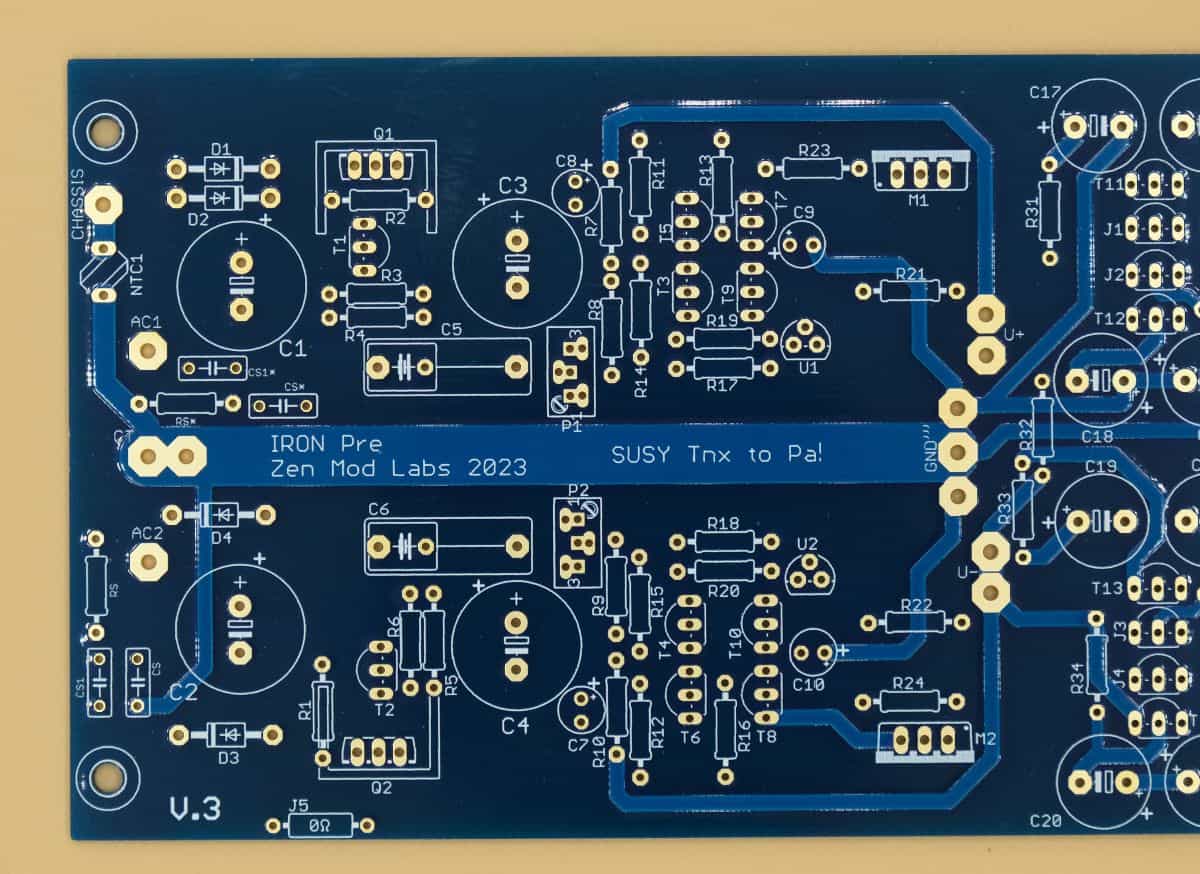
Circuit power supply
Rectifier/voltage regulation
transformer 600/600
Cinemag/Jensen/Edcor
Zen Mod has provided additional solder pads for a volume control. The These pads help ensure that a DIYer can be content knowing that they have an exceptional preamplifier in their possession.....
Input circuit
cleverly solved
.....Provided they don't use an inferior volume control. But we know how to prevent that (LOL).
Volume control with Muses
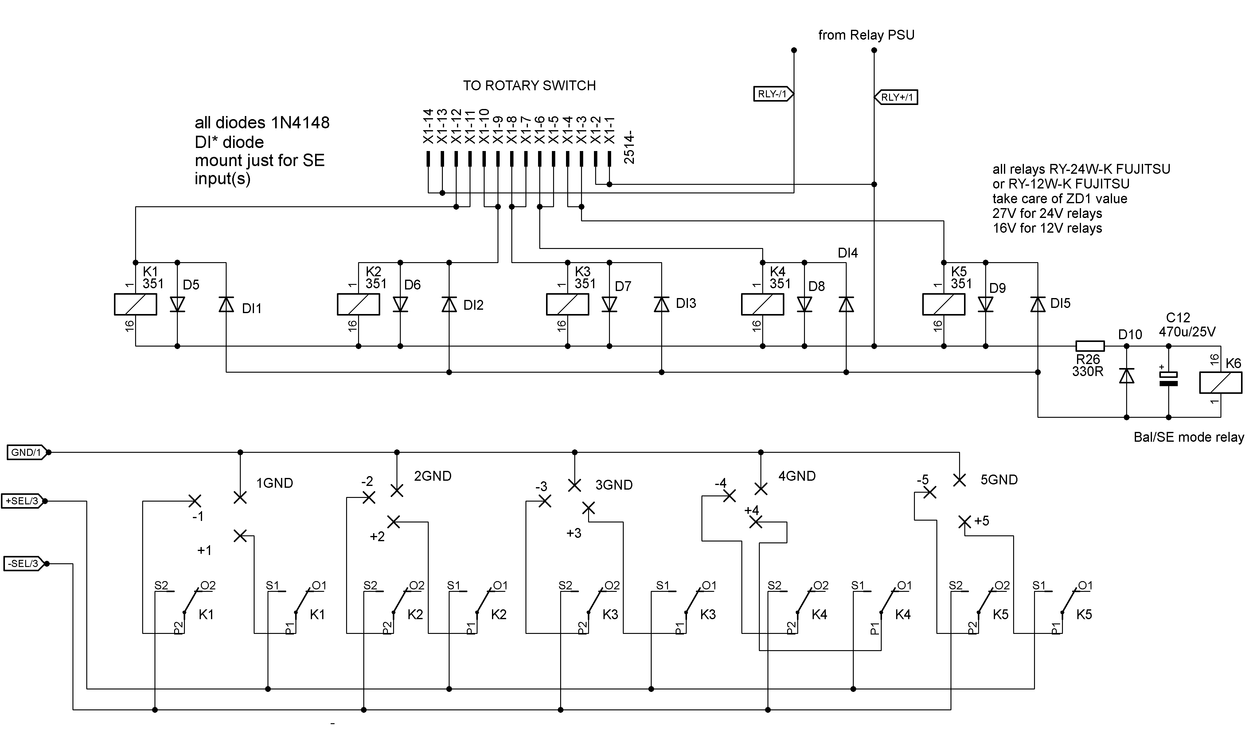
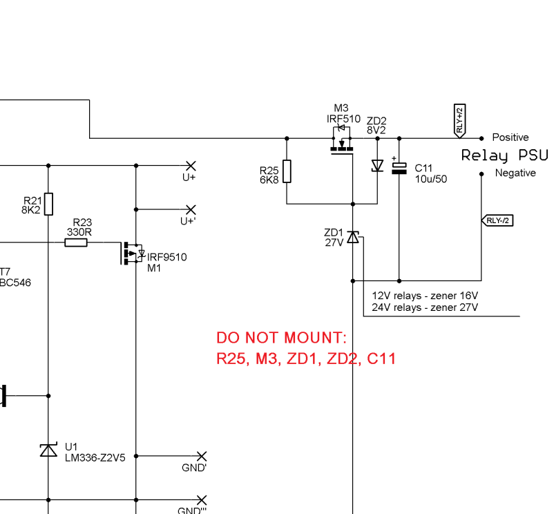
After brainstorming with Patrick and my prospective customers, I decided to develop my own solution for the Iron Pre. The relays were already available, so the input board could be omitted. However, in the original circuit, the relays are at GND. So, if I wanted to adopt my solution, the circuitry had to be changed. This was one of the first questions in the special Thread "Logic Solutions for Iron Pre Kits"
Zen Mod solved the problem by explaining the necessary modification without further ado. A change was then included for future boards to operate the relays at V+.
Power supply
Changes SE
Changes balanced
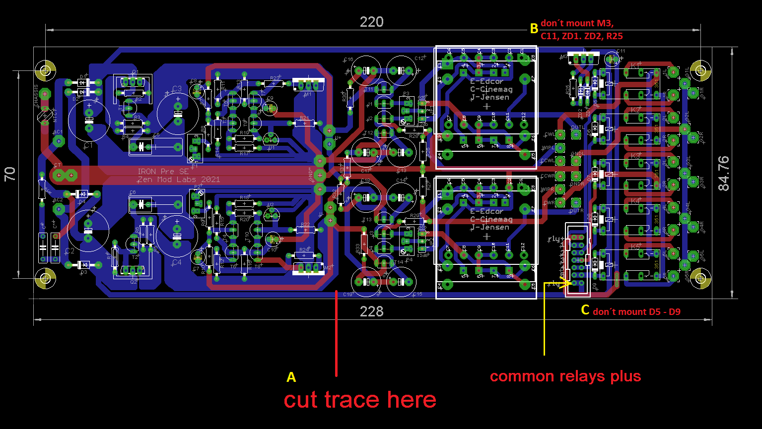
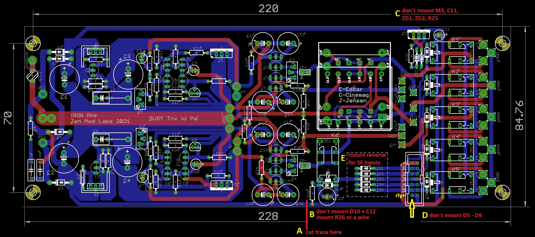
For the SE version, steps A to C must be followed. Steps A to E must be followed for the balanced version.
After a few weeks (it felt like only days) these boards were on my desk. Patrick had sent me a complete set for a balanced Iron Pre, as well as an empty board for the SE Iron Pre.
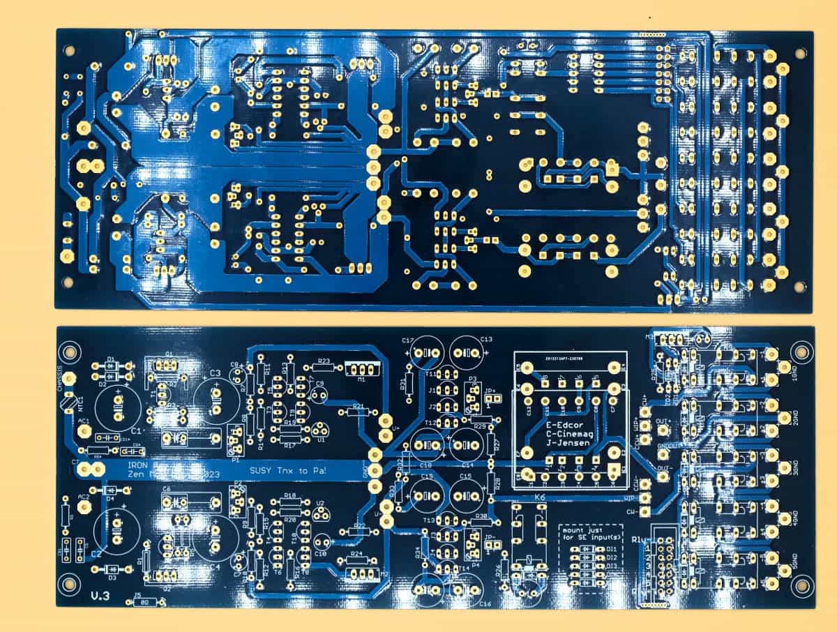
Iron Pre V 3.0
balanced Version
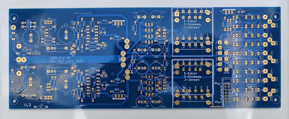
Iron Pre V 3.0
unbalanced Version
Power Supply
each identical
Important - If you intend to use this Muses solution with your Iron Pre, it is critical that you know which version of Iron Pre boards you have. Please ask directly or ask in the diyAudio forums if you are unsure. Boards noting 2021 have the relays at GND. There is no version notation on the 2021 boards. Boards noting 2023 have the relays at V+. The version as of this writing is V.3.
V3.0: When using the Muses solution, the components (J5, M3, R25, ZD, ZD2, C11) for the power supply of the relays must not be mounted. The required voltage is provided by the MC-board.
The solution presented here is compatible with all boards. Small modifications may have to be made.
The Muses board
Since the Iron Pre already has short signal paths, I decided to bring the Muses chip as close as possible to the signal. Because of its construction a direct soldering of the chip is not possible. It needs a carrier board. Because there is not much space available, a vertical board was chosen. The idea of a female connector on the solder pads intended for the potentiometer was torpedoed by the given grid dimension. Additionally, the different solder pad distances for the balanced and unbalanced added a challenge.
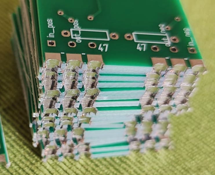
A short inquiry with the boss gave me the exact distances but left me alone with my thoughts. Maybe instead of a header, a strong angled wire for the connection and simply set up the Muses board vertically? Why actually a wire? Coating the narrow sides of a circuit board is now common practice, isn't it?
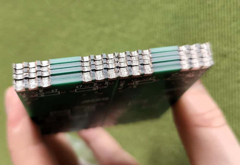
No sooner said than done. Defining the appropriate vias on the lower cut edge produced exactly the desired effect. A 3D simulation showed a side edge that can simply be placed on the board of the Iron Pre and soldered. The whole process is called castellation, by the way. Note how the spaces look like the top of a castle.
But there are some other requirements. The power supply and the SPI bus.
The Muses already feels comfortable with the +/-15V of the Iron Pre. Since the current required by the Muses is rather low, we can do without an additional power supply. A three-pin connector in the direction of the power supply establishes the connection.
However, we need another voltage (+5V) for the digital part of the Muses. A fixed voltage regulator quickly placed on the Muses board serves the desired purpose. We will also use the +5V supply for another purpose.
This brings us to the SPI bus. With the bus we transfer the data to control the Muses chip from the microcontroller (MC). To separate the digital and analog part electrically, I use a digital isolator. However, for this we need two power supplies; input and output channels of the digital isolator are electrically separated. A very nice side effect with this is that a balanced power supply is not cancelled out. If I would supply the Muses chip from an external power supply, I would have to build up these voltages twice.
So, the bus needs a 5-pin connection between Muses and MC board. I placed this in the opposite direction of the power supply connector.
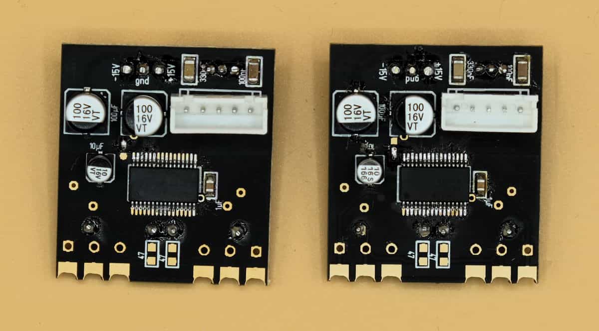
Here are the first impressions of the Muses-board:
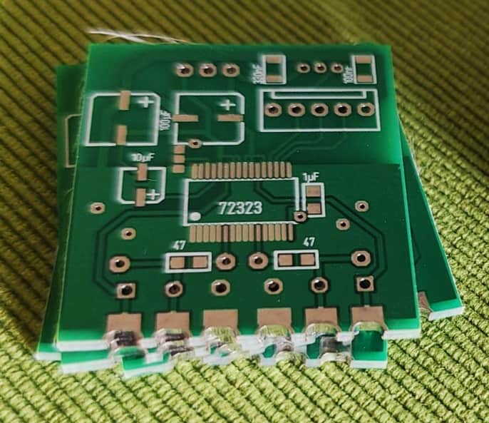
Muses board
unbalanced (SE)
Muses board
balanced Version
Side view
castle crenellations
Note the different distances spacing within the castellations for the balanced and SE. If soldering the Castellation connection seems too vague or wobbly, you can also use a piece of wire in the corresponding holes.
There is now a new version of the balanced Muses board:
Muses board
"new" balanced

Muses board
"new" balanced
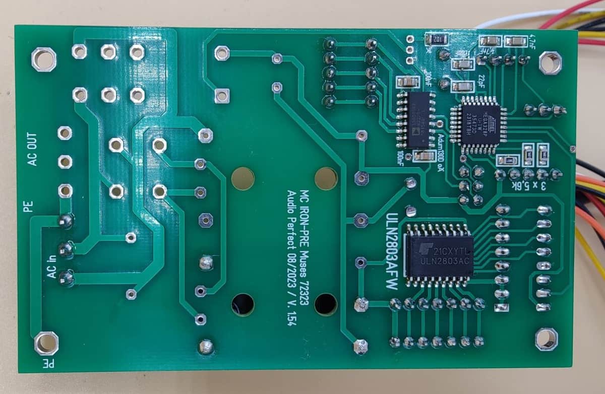
The microcontroller board
Here I fall back on my already existing MC-board with some Iron Pre specific modifications. Since the software is now mature and tested many times, the MC AT328P will remain. The 2.6 inch Digole (320x240) display, the Bourns encoder, and the IR sensor (TSOP4836) also remain. What also remains is the power output (approx. 1600VA). This relay must be fitted in any case, as it switches on the power supply of the Iron Pre is switched on. An additional consumer (power amplifier, etc.) can also be switched on with this relay.
A standby transformer is not needed, as the required power supply unit already has a low current consumption in idle mode. The analog power supply is now also not necessary, because the Muses chip is now supplied by the Iron Pre power supply. The connection to GND has also already been realized on the Iron Pre board, to these parts fell victim to the red pen.
Additionally, there is a second 5-pin socket for the SPI bus. With the balanced version, logically two Muses boards must be supplied. Likewise, there is there is a corresponding 7-pin connector for the relays. Since we can switch the relays in the digital domain, we need only six lines; V+ and five return lines. The seventh line can be used for another purpose, but it has to be programmed accordingly. Instead of the 14-pin connector the Iron Pre board now gets a 7-pin connector which corresponds to the MC board. The protection diodes of the relays on the Iron Pre boards are no longer necessary, because the driver chip (ULN2803) already has them built in.
The Iron Pre is typically built with 12V or 24V relays when used with the standard input switching. With the Muses solution, 5V relays can be also used. The advantage would be that a 2nd power supply unit is not required. If you are modifying your existing Iron Pre with existing 12V or 24V relays, a 2nd PSU can be installed to generate the voltage required by the relays.
Wishes from the forum:
It was requested that the power supply IRM-02 series from Mean Well should be usable. i have extended the PCB to this effect. In addition, I have set the mounting holes so that they are within a 10x10mm grid.
I don't want to forget to mention that the MC-board can be operated with a voltage between 80 and 285V AC. With using the Mean Well power supplies, the range of usable input voltage is even higher.
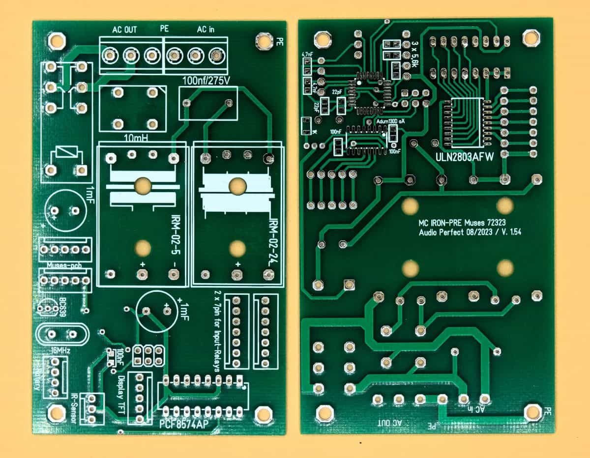
MC-Board
Dim: 100(3.9) x 62mm(2.44)
MC board
one 5V Mean Well mounted
MC board
Bottom
This is the current version (1.59) of the microcontroller board:

MC board
Blank circuit board

MC board
Equipped symmetrically
Assembly
Please read this section carefully and completely before starting to assemble the board. These instructions is tailored to the installation of the Muses solution. If you want to set up the PreAmp with a conventional tap changer and potentiometer you will also find tips here on how to set it up.
Hints for mounting
As with every project, we build from small to large. So diodes and resistors first, followed by semiconductors, film capacitors and finally and last but not least the electrolytic capacitors. Don't forget to mount the heat sinks and the connectors for the jumpers.
In order to be able to solder in the Muses board without problems, the transformer(s) should not yet be installed. This way the soldering pads are easily accessible from both sides.
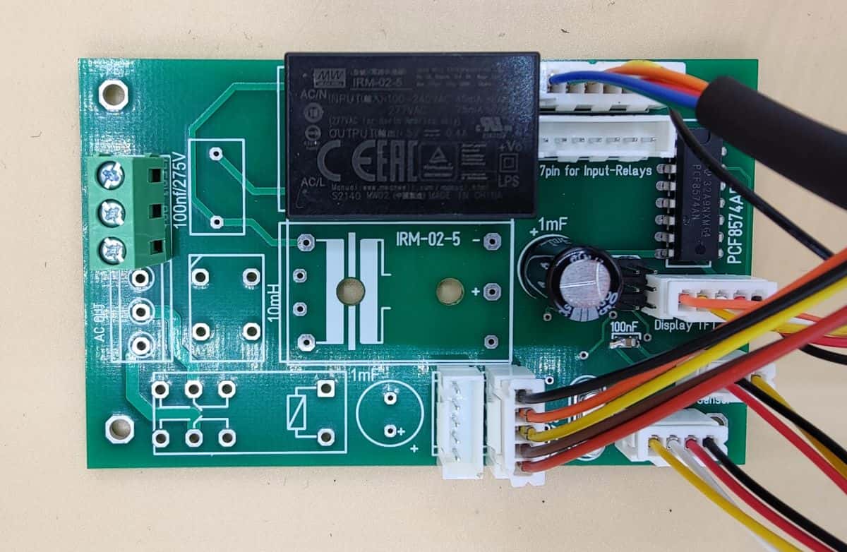
I start with the power supply. This has the advantage that a possible defect caused by an incorrectly soldered component cannot destroy the next part of the circuit. After assembling the components, I connect the power transformer and check the function of the circuit.
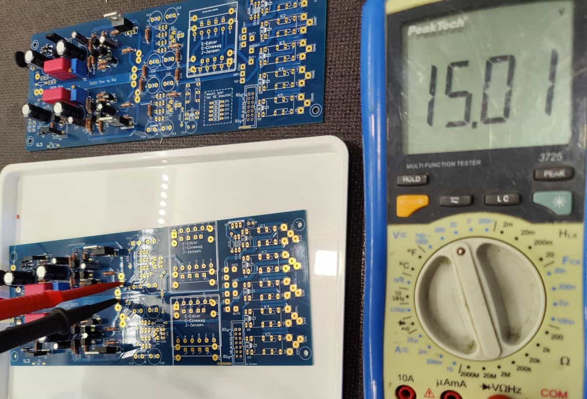
mounted PS
adjust +/-15V
With the precision trimmers, the voltage can be easily adjusted to the required +/-15V.
By the way:
I use a mains transformer with 2 x 15VAC (30VA). Due to the low power consumption, the idling voltage is so high, that the rectified voltage before regulation is over 19V.
Please remember to disconnect the transformer from the mains again after the adjustment procedures. You should also give the circuit a few the circuit a few minutes to discharge the electrolytic capacitors.
In the same order I now equip the rest of the amplifier circuit. As already mentioned, the transformer(s) and the relays are and the relays are still left out.
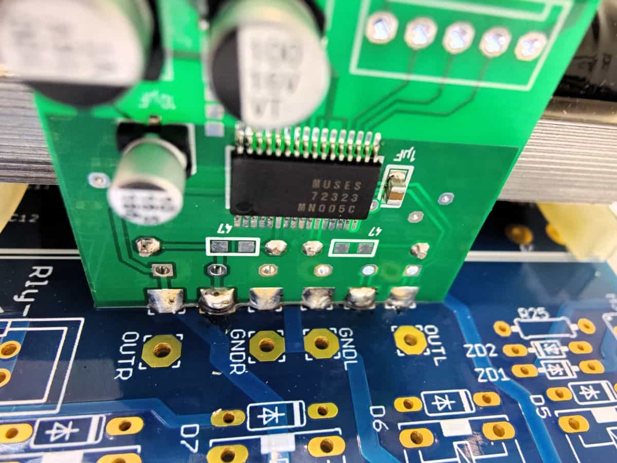
Installation Muses Board:
Now it's time to install the Muses Board(s) (further referred to as MB). The MB will be shipped fully assembled (incl. SPI bus connector and power supply). For the balanced MB, the solder jumper should be soldered accordingly. As you can see, I unfortunately did not stick to my own specifications and made soldering the connectors a bit more difficult for myself.
Muses Board
strong support
CMF 55
Easy to reach solder pads
Narrow
but no contact
Before the actual fixing process, one of the six solder pads for the external potentiometer (preferably an outer one) is wetted well with solder. The hole should be allowed to fill up. Please note the mounting position of the MB. The 3-pin plug should point in the direction of the power supply. Now heat the already tinned solder pad again and place the MB in the liquid solder. The MB will be placed on the PCB at a 90 degree angle so that the solder pads of the MB are aligned with those on the PCB. By heating the solder again, the position of the MB can be corrected. When I am satisfied with this, all solder pads can be soldered. The pad that was soldered first is filled last. When all the pads are soldered/filled, the result is a very stable construction.
Satisfied? Now the remaining components such as relays and transformers can be assembled. The transformers have a mounting direction. They should fit well in the holes. The power supply for the MP can now also be made. Before soldering the relays, please solder the connecting cables to the output sockets. If the relays are already equipped, soldering the cables is difficult.
The protective diodes for the 5 input relays do not need to be fitted. If you are building the balanced version of the Iron Pre and want to use unbalanced inputs, please equip the short-circuit relay for the negative signal WITH a protective diode. In addition, the diodes for the corresponding unbalanced inputs must be fitted.
The socket for the connection to the control of the relays is soldered in the position of the 14-pole socket. The 7-pole connector (SE version 6-pole) carries the control signals and the external supply voltage.
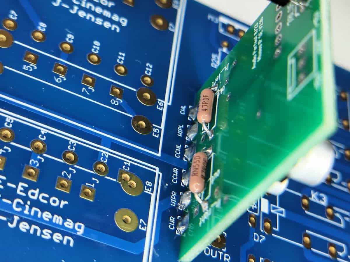
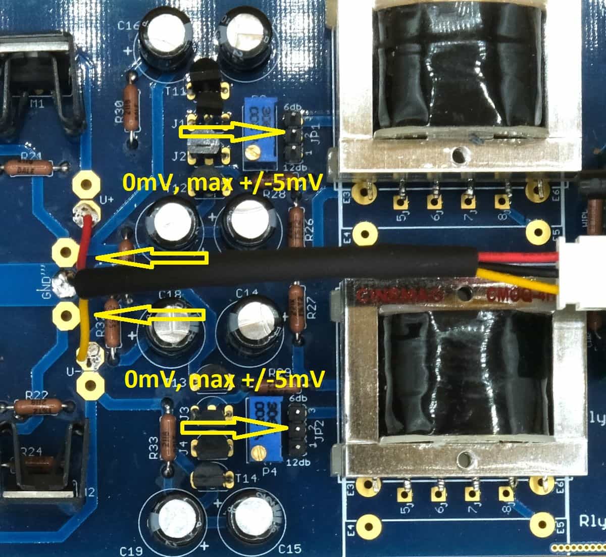
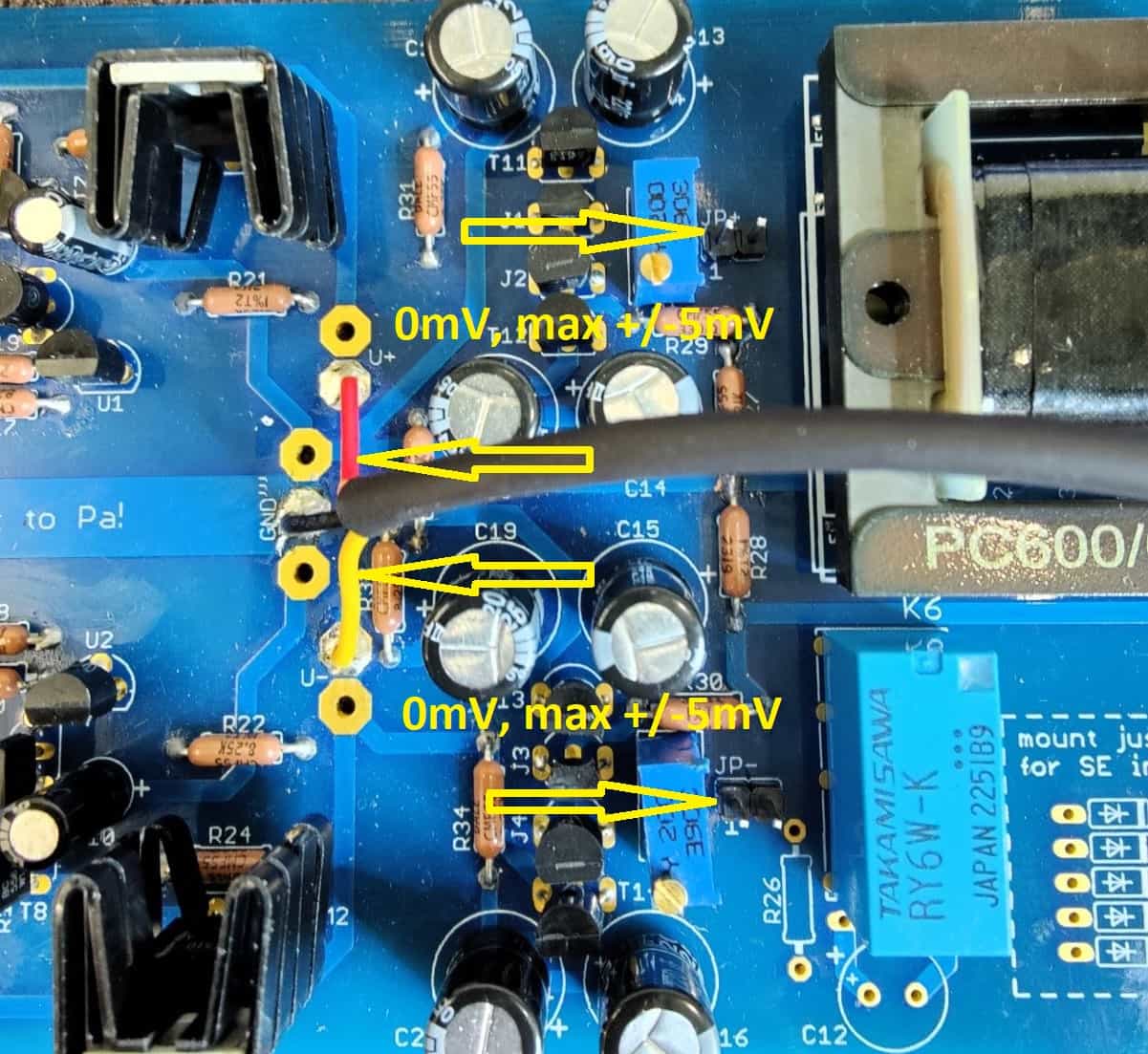
Setting the offset:
Now it is time to set the offset. This means that no DC voltage should be present at the input of the transformer. This would unnecessarily saturate the transformer. The transformer may respond to this with hum, but in any case with a reduced output capability. This setting is made via the 22-ohm trimmers. We try to set this voltage to 0mV. According to the DIY forum, up to +/-5mV is permissible. I had no problems to reach 0mV.
SE Version
0mV (max +/-5mV)
SE Version:
We measure the voltage between the middle pin of the 3-pin connector (6db/12dB) and gnd. Please make sure that no jumper is plugged in. This establishes the connection to the input of the transformer. With the trimmer we can now set the voltage to 0mV. We have to do this for both channels.
Balanced Version
2-pole connector
Balanced Version:
Here we have one 2-pole connector per signal (positive and negative) (connection amplifier circuit/transformer). No jumper must be plugged in for the measurement. We now measure the voltage at the pin connected to the trimmer. Here, too, we measure against gnd. The voltage can be easily adjusted with the trimmer. We make this setting on two boards and there for both signals.
That should be all there is to it. Now the connections to the input and output sockets have to be made. This is described in more detail in the section on enclosure construction.
- SPI bus 5pin cable (balanced 2X)
- Display - 5pin cable
- IR sensor - 3pin cable
- Rotary Encoder - 4pin cable
The connecting cables to the MC board are simply plugged in:
Other:
I would recommend testing the finished boards for function before installing them in an enclosure. To do this I connect a pair of input sockets and the output sockets provisionally with a cable configured for this purpose. In this way a simple listening test.
Do not forget to plug in the jumpers. For the SE version, this sets the maximum amplification.
A special feature of the balanced version is that inputs can be configured as SE by soldering in a Zener diode. For this purpose, a relay (SE/bal) is provided, which in this case applies the negative signal to gnd. It is important to to know that this relay (when not activated) connect the transistor circuit with the transformer. This means that this relay must be installed for the Iron Pre to work properly. If you want to do without SE-inputs, you can also bridge this relay with a wire, so that the negative signal connection is permanently established.
The following section (download documentation) explains how to select the assigned input.
Software
After starting the unit, the welcome sequence appears. After approx. three seconds (for new installation) the main screen appears.
In the meantime I have explained the software on various sites and also made a quite decent documentation for it. These you can get here or below in the Download area
A few more impressions follow:
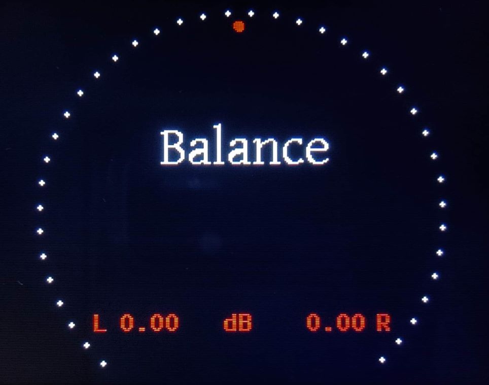
Balance
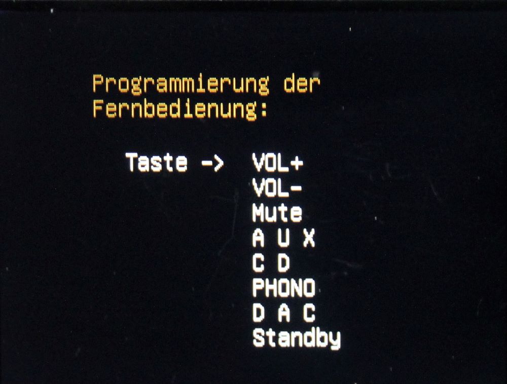
Remote control
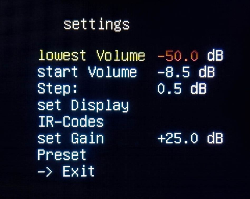
Options
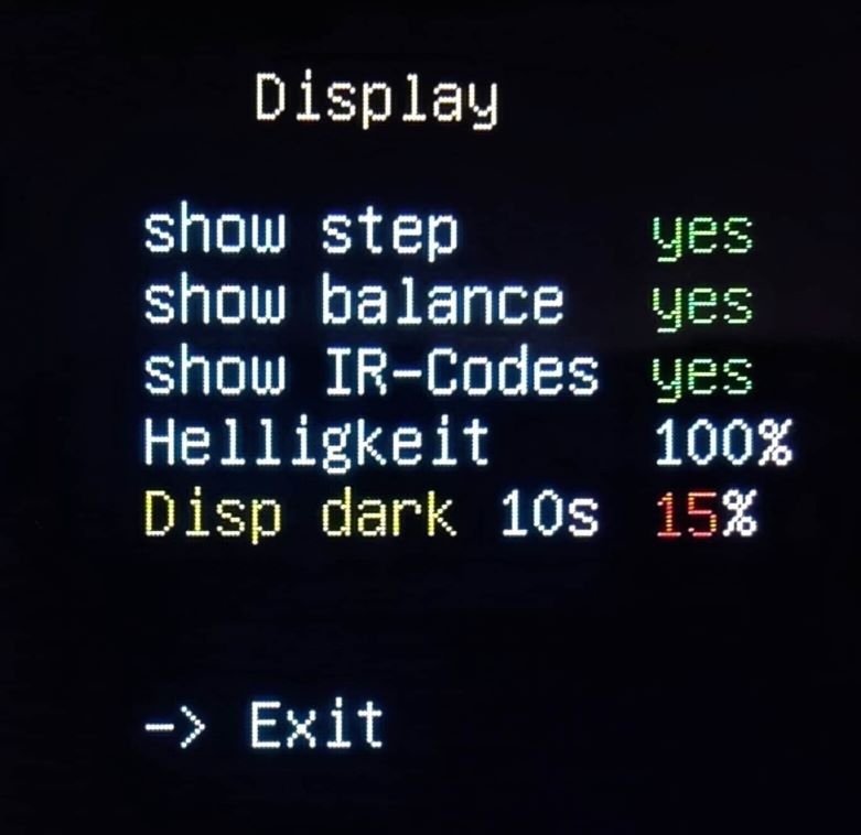
Options Display
In one post, the coarseness of the fonts was mentioned. I would like to counter this statement here. All pictures were taken with a very small distance. This is probably why this impression was created. When viewed normally, the fonts are are very sharp and easy to read.
Unfortunately, I have to use the manufacturer's fonts. A font upload has not worked so far. I am currently in contact with Digole to integrate another font.
enclosure construction
Lorem ipsum sapientem ne neque dolor erat,eros solet invidunt duo Quisque aliquid leo. Pretium patrioque sociis eu nihil

Total view
Lorem ipsum sapientem ne neque dolor erat,eros solet invidunt duo Quisque aliquid leo. Pretium patrioque sociis eu nihil
Upgrades/Updates
In order to be able to cover all variants of the Iron Pre, I have to offer several variants with different component costs. For this reason, I have decided in favour of modular pricing. The most common variants are offered here. If your set looks different (relay voltage), please let me know before ordering.
All sets include the IR sensor, rotary encoder, 2.6 inch TFT EPS colour display from Digole, cable set for rotary encoder, IR sensor, display, relay control, SPI bus and power supply Muses board.
Price list:
- MC-board with two HiLink/Mean Well (5V and 24V) and 1 Digital-Isolator
- 1 x Muses-board 72323
- 167€
unbalanced version (SE):

unbalanced Complete set
- MC-board with two HiLink/mean Well (5V and 24V) and 2 Digital-Isolators
- 2 x Muses-board 72323
- 202€
balanced version separate power supplies for both channels:
On request, a "volume control only" without display is now available for the unbalanced version:
- MC-board with Rotary Encoder and IR-Sensor
- 1 x Muses-board 72323
- Cable set
- 120€
unbalanced version (SE) volume control only:

only Volume Control
unbalanced Complete set

MC board
Shipping costs by arrangement.
Some will think the price is fair. Others will criticise the fact that this is a DIY forum and the price is quite high for a DIYer. Please consider the effort I have to put into creating a set. Additionally I have to In addition, I have to pay tax on the income, keep parts on hand and spend time on support.
Downloads
The assembly instructions will be provided after completion of the project.