His Master's Noise: A Thoroughly Modern Tube Phono Preamp
realised by Frank Wilker
This project is developed and tested!
last changes: 01.01.2020
- design by Stuart Yaniger (SY)
- on diyAudio
- posted at the 21. April 2010
The Power Supply
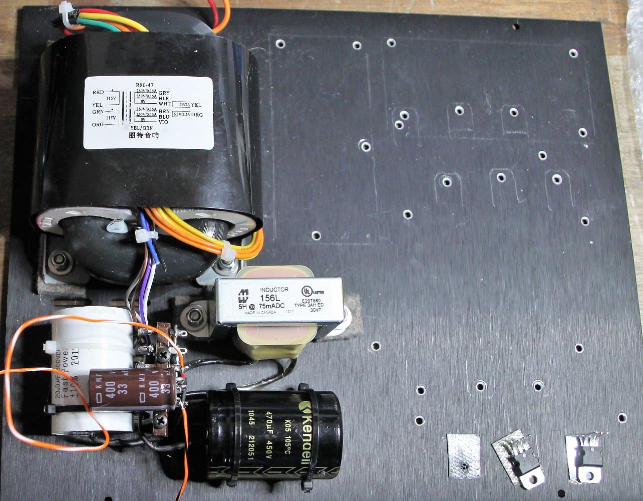
Here is a classical CLC-filtering used. Behind the rectifier follows a small cap. I used a 60 uF foil-cap. Next is a choke with 5 Henry/ 80mA. I use a choke from Hammond. The type matches the 5H and 80mA, is cheap and easy available.
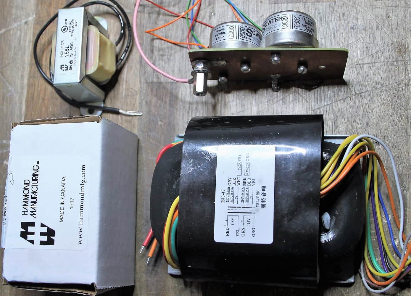
R-Core transformer and choke
The used Iron
The requierement 80mA could be dangerous
So I had a damaged choke. I think, the heat of a additional used Resistor for increasing the input volatage and the heat of the choke. The choke was destroyed and so i use now a choke for a higher load (currant 150mA). This choke has a higher resistance and reduces the input voltage. So the additional resistor is not needed anymore.
I used behind the choke a 470 uF/500V electrolytic cap. From here i´m going to the ps-pcb.
I prefer when only small power (up to 100VA) is needed as transformator a R-Core-Type. You´ll never hear them working. And the emission is very small. But the magnetical emission is there and you´ll here from it a few sentences later. The mounting will be exactly explained in the stage "mounting in the housing"
The Power Supply PCB
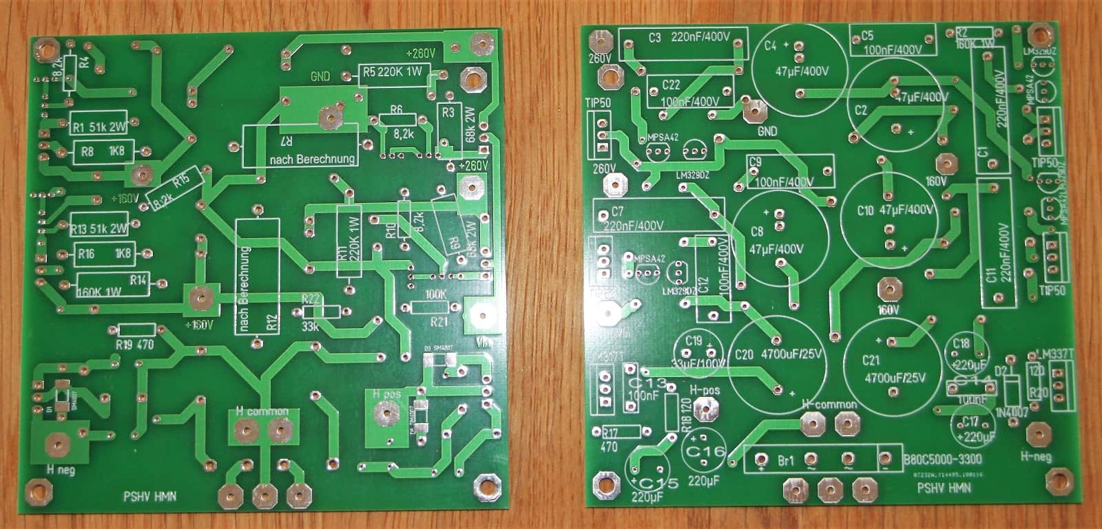
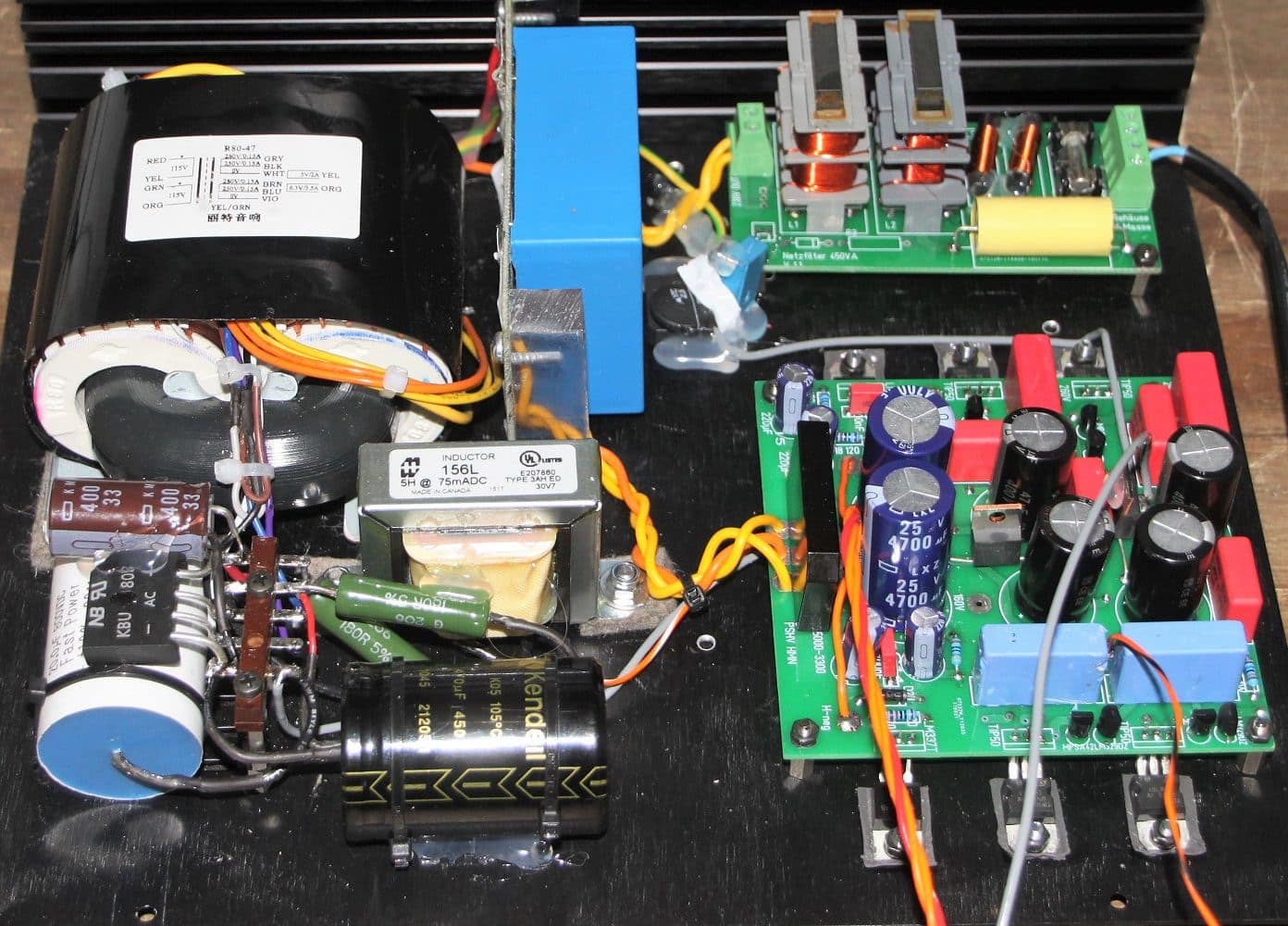
The 100x100mm power supply board contains all the components required for the heating system and the four supply voltages. SY (Stuart Yaniger) requires one branch for each voltage and each channel. So we need 2 x 260V and 2 x 160V. The raising of the Tube heating was also realized on the power supply board. This is not the case in the picture above. The capacitor for lifting up of the heating voltage is still on the main board. The resistors underneath the circuit board.
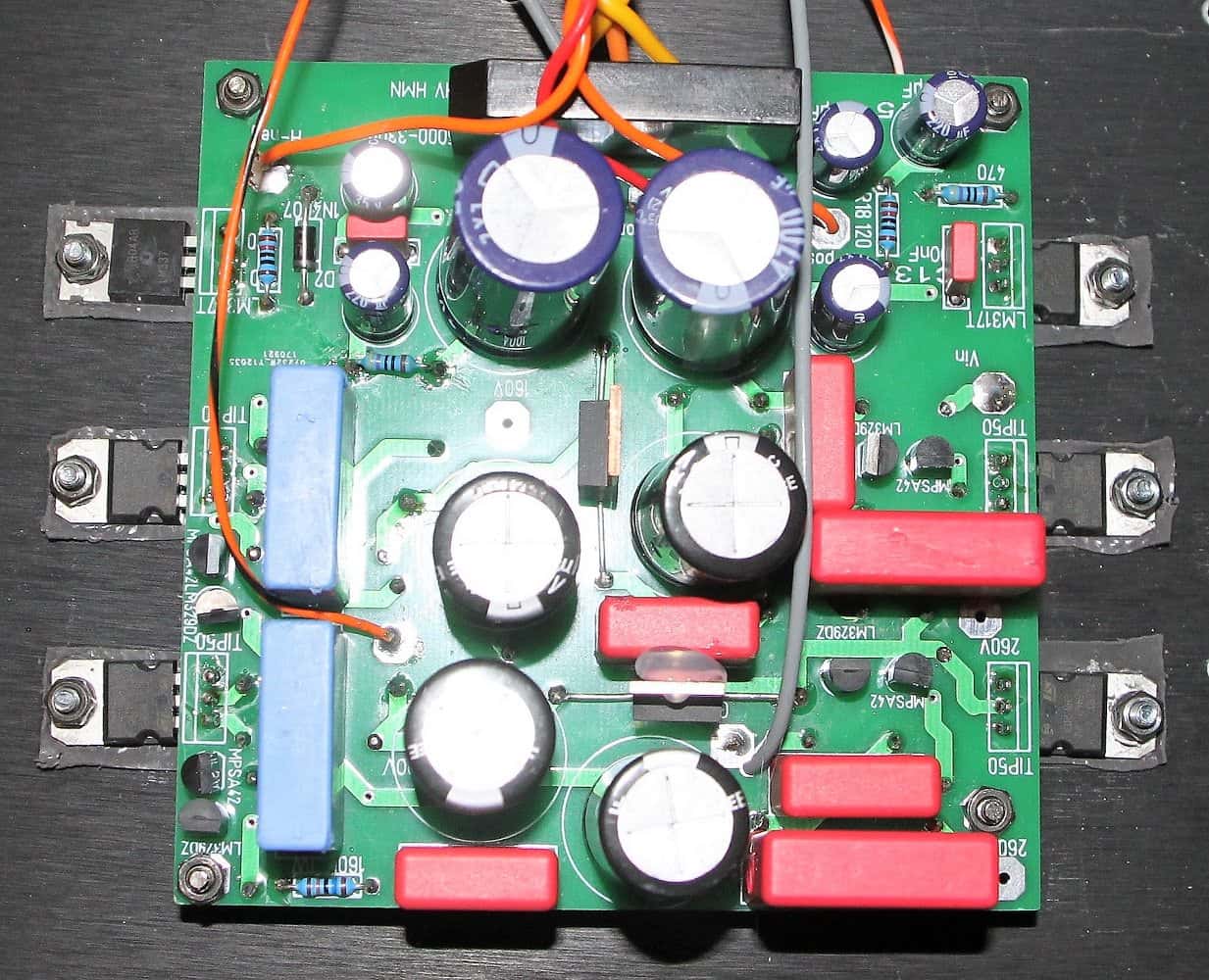
Power supply board
completely wired
The heat sinks of the power transistors and voltage regulators must be mounted outside the circuit board. I have chosen allows you to simply screw them onto the case back, as the heat development is relatively low. In the end I have to admit that you have to unscrew all semiconductors in case of a defect. A solution with heat sinks on the circuit board would probably have been easier.
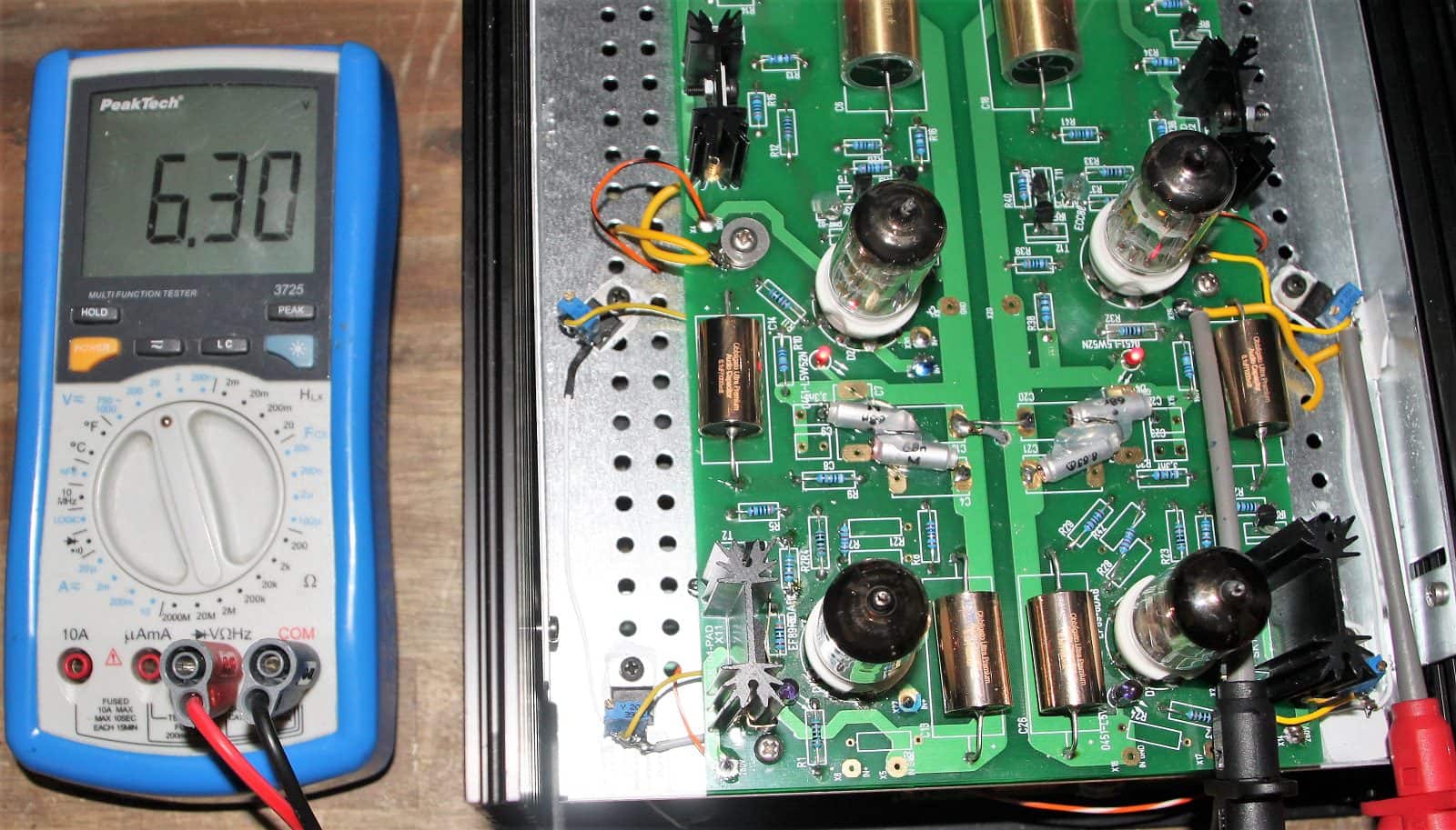
Heating system
perfectly adjusted
The heating variant was a bit too complicated for me. Since my son is building another device, we took Allen Wright's tip and implemented the heating voltage supply via an LM317 voltage regulator per tube. This allows the heating voltage for each tube to be set exactly.
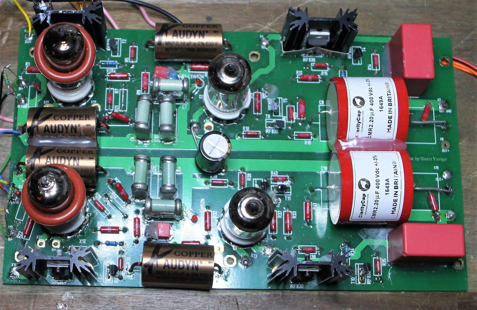
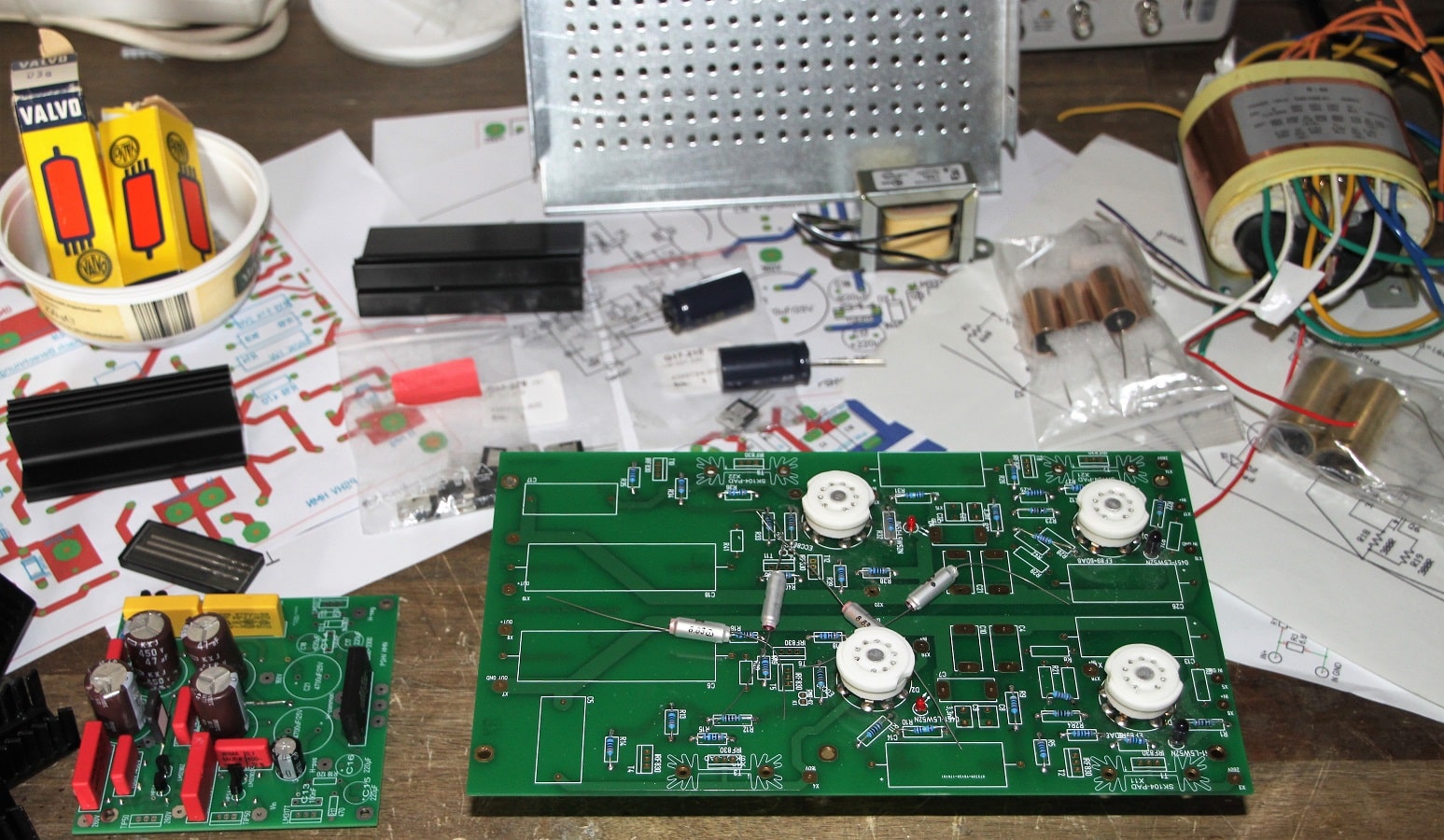
Die Hauptplatine
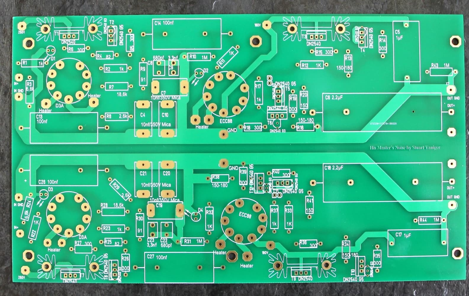
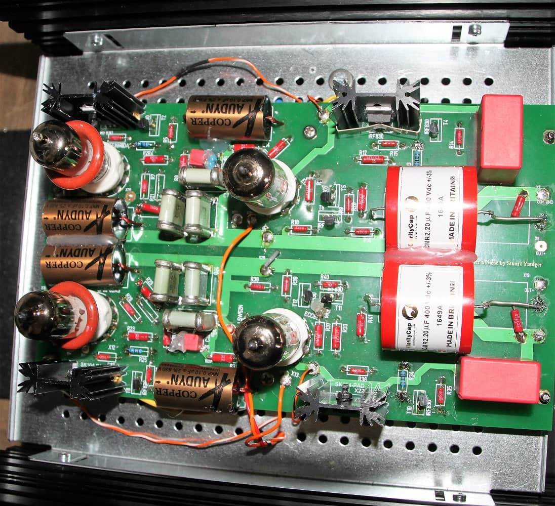
Main Board
It is assembled as usual: from small to large. First the resistors, then the LEDs, glow lamps, TO92 transistors, sockets for the tubes, capacitors and finally the heatsinks with the DN2540 in TO220 design.
If you follow my recommendations for the resistors and then use narrow-tolerant capacitors for RIAA equalization, you can dispense with great measuring procedures. The deviation of the RIAA curve for me at 20kHz is a maximum of 0.5dB.
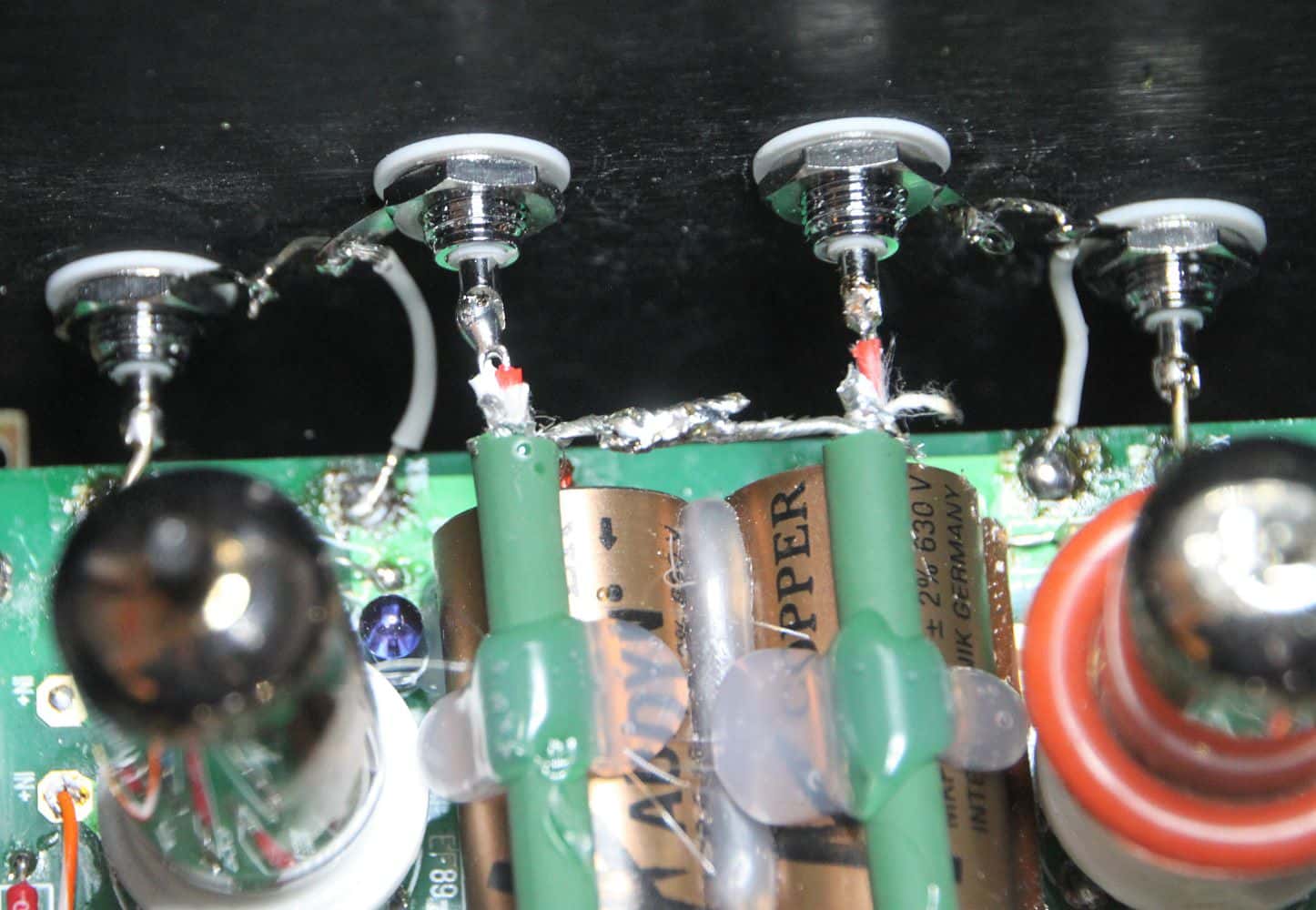
Complete the cabling for the tube heating now. One pin of the heating of each tube is connected to GND_Heating. Then the other two heating connections of the tubes of a channel with +6.3V. On the other channel, connect the remaining two connections with -6.3V.
Whoever now complains that he has to make an external cabling, although we have such a nice circuit board, should note that relatively high currents flow here. This current flow on the board should be avoided at all costs, as it could influence our valuable audio signal.
The design of the circuit board is not laziness, but intentional.
Tests and commissioning
Please always remember. The tensions with which we work here are L I F E - T H R E A T E N I N G ! ! ! Beginners are usually more careful than the "old hands". But that doesn't change the fact that both of them can't cope well with the high tension. So please be very careful.
Due to its design, this power supply unit is relatively sensitive to being switched on again when a high voltage is still present. I killed one of the power transistors twice. So always wait until the capacitors have discharged.
Now comes the exciting part; a little play on words so to speak. Before we connect the power supply board with the power supply, we first check the voltage behind the choke. So we put a load resistor on it and go.
Even a reminder. A load resistor causes the voltage to drop after switching off. Otherwise the voltage is maintained for a longer period of time (weeks to even months). This can be very unpleasant. Above all, you cannot continue working if there is still a high voltage present.
We need at least 310V to have enough voltage surplus for screening. At 310V and approx. 80 mA we need a resistance of 310/0.08; exactly 3.875k. Probably we do not have this and also a slightly higher voltage. So we take 5kOhm. This results in a current flow of 64mA at 320V and thus a power of approx. 20W.
Please ensure that the load resistance is appropriate. When switching on briefly, measuring and switching off again, it is also possible to approach the load limit closely. Connecting resistors in parallel and in series often helps if the suitable resistor is not available.
Has everything worked? The transformer doesn't get too hot? And doesn't hum either? Then the power supply board may be connected. Now we need four load resistors. For the 260V we need 260/0,02 = 13.000 Ohm. With a 10K resistor (mostly well available) we reach 26mA and consume about 6.8W.
For the 160V section 160/0.02 = 8k = 3.2W applies. I had 7.5K resistors (21.5mA) available. Please remember. All high voltage parts have load resistors.
We now switch on briefly. And immediately off again. If there hasn't been a bang or a braising, we measure whether there is now a (probably small) voltage across the load resistors. This voltage should not be too high yet, because the voltage slowly increases.
If everything's okay, we'll turn it back on. I have already connected the multimeter to a load resistor and control the voltage rise. If nothing obviously gets hot now, or even smokes, I measure the voltage over the other load resistors.
Fortunately, I had no case where the high voltage power supply did not work properly immediately. As I said, always wait after switching off until the power supply is completely discharged.
Now we connect the tube heater as described above and check the voltage at the heating connection of the tubes. Please also be careful here, as the heating voltage is applied to the high voltage.
If everything is okay here, we short-circuit the input of both channels. Just solder in a wire bridge between input and GND.
Finally the time has come. Now we can power one section of the motherboard. I always use a 10Ohm resistor to make the first voltage connection. This makes it relatively easy to control the current flow. At the desired 20mA we then have a voltage drop of 200mV, so a low power. Even a 600mW resistor is sufficient.
Now we measure again:
- 1. voltage drop across R2/R23 . This should not be more than 20V.
- 2. voltage drop across the IR diode. This should be approx. 1.2 V. My IR diode gave me 1.4V. This is also okay.
- 3. The voltage at the anode of the D3A. This should be about 140V.
If all is well, then we continue with the D3A of the other channel. Also here we carry out the above mentioned series of measurements.
Now it's going to happen in quick succession. By connecting the 160V, also here via a 10Ohm resistor, to the E88CC, we put two differently switched electrical systems under voltage. The 1st system provides the voltage amplification. The 2nd system acts as cathode follower.
Each system should have a current consumption of max. 10mA. First we measure Iges over the 10Ohm resistor. Here should not drop more than 200mV (20mA total). Also here we measure as described above, but only for system 1: 1. voltage drop over R, 2. over the red (I take yellow) LED and 3. the anode voltage.
For System 2 we determine the current flow as follows: We simply subtract the current flow of the 1st system from Iges. The current flow of the cathode follower remains.
All values in the green range? What exactly is the green area? The discussion in the thread is very far-reaching. SY itself posted back then that a shift of the anode current of the input tube up to 10mA was not associated with a deterioration of the sound image.
Now we should also test the device. Sockets and plugs soldered on and connected to system and amplifier.
Satisfied? Or rather not? Remember that first of all the input resistance must be adapted to a possible transformer. And secondly, capacitors often require a longer break-in time. So first listen for a few hours and then rate the performance.
Installation in the housing
The housing I use is manufactured by Modusshop 2000 from Italy. The cases have a good quality and they are available in many different sizes and variations. I prefer the cases with aluminium bottom and lid. These are easier to work than sheet steel lids. For optical reasons I also choose the 10mm front panel.
An intermediate plate provides additional stability for the housing and mechanically separates the power supply section from the main board.
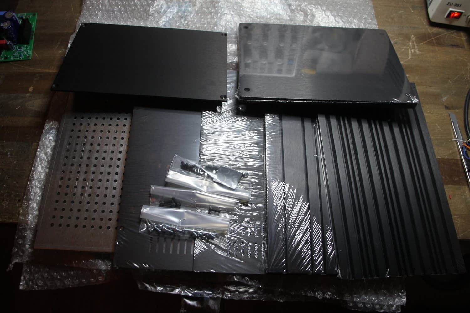
housing
still packed
Power supply
Power supply
completely screwed
A short conclusion to my variant: Today I would install the power supply in a separate housing. This costs a few Euro more, but has the advantage of working better. The installation of all components was a bit tricky. It got even worse when I had to change a defective choke.
In my first attempt I had the power transformer mounted in the back of the case, underneath the cinch sockets. Don't do that. Despite the R-core transformer, there was a humming noise, not too close. So transformer to the front directly behind the front panel.
Do yourself a favor and test beforehand how the components are best installed. I have provided everything with relatively long cables, connected them to the amplifier and turned it up properly. Then I carefully moved the transformer and choke so that the hum was lowest.
You will quickly notice which arrangement produces the least hum. Please be very careful and do not touch live parts. Once you have found the right arrangement, you can start machining the housing.
I drill the holes for the choke, power transformer, PCB, transistors and holders for solder lug strips. Then I attach the mains transformer. From there I make the connection to a solder lug strip where I then solder the rectifier and the foil capacitor.
From here it continues to the throttle. The electrolytic capacitor is soldered behind the choke. I always glue the capacitors with hot glue. Protruding cables are tied together with cable ties. However, I avoid connecting the AC cables with the DC cables. That gives only again trouble (Hum).
The circuit board continues. If the input voltage is too high (well above the required 310V), I put a resistor in between. This protects the transistors, but also generates heat. Before I screw on the board with the transistors, I provide them with all necessary cables.
Only use sensible cables. I like to use teflon sheathed silver cables. Now screw the board onto the base plate. Then the transistors are connected. These have to be insulated with mica plates or Teflon foil. Do not forget the plastic nipple for the screw. Once the transistors and voltage regulators have been installed, the power supply unit is ready.
We now check the insulation of the semiconductors. With a multimeter we measure the passage between the semiconductor (metal plate) and the screw (or a metal part on the housing). It must not be possible to measure the passage here under any circumstances. Afterwards I check the power supply again with load resistors or connected main board in order to be able to exclude a defect.
main board
on the intermediate plate
Okay, now a cup of tea so the power supply can discharge.
Of course we can also screw the main board onto the intermediate plate.
I fixed the board very close to the back wall. This way I can keep the signal path very short if the input sockets are mounted accordingly.
I'll put the output jacks over it. As connecting cable I use the Sommer Cable SC-Albedo MKII.
Cinch connections
I use a conductor for the signal, a conductor for GND and the shielding I connect at the most sensitive side with the housing. The shield is only electrically connected on one side. There is also no discussion. This is not a ground cable.
I glue the cables again with hot glue, but only if the device works really well.
So, shut up, monkey dead and turn it on. Have fun with it!
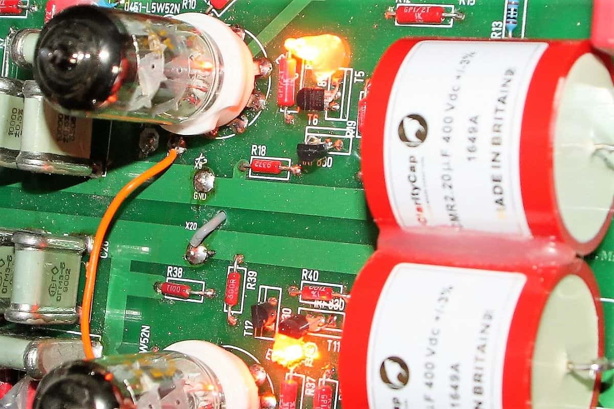
neon lightning
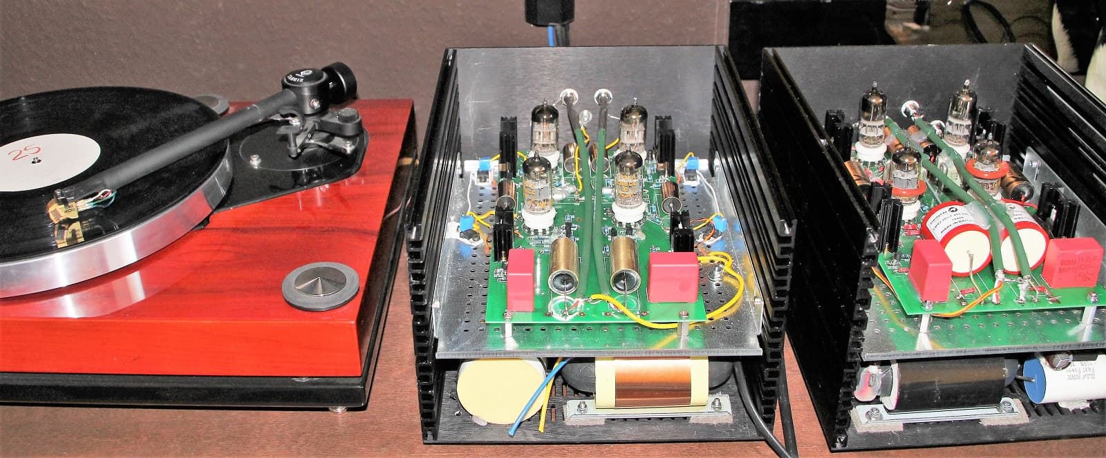
in operation
Living style
the beginning
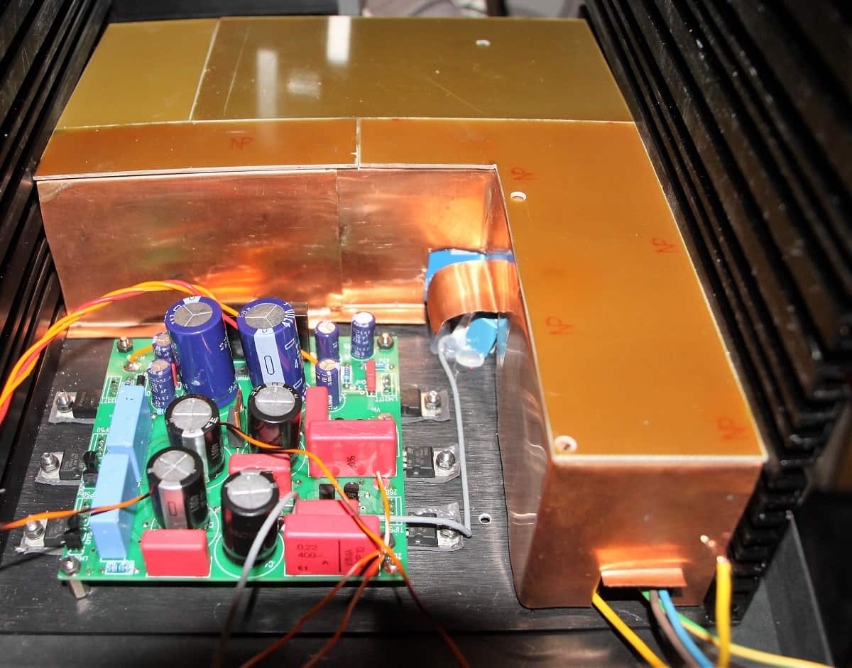
shielding
copper sheets
Tips
What other tips can you give? Write to me. Otherwise I like to glue the capacitors in one place with hot glue. When moving the capacitors you will probably have noticed that some parts cause a noise in the loudspeaker when you touch them. You can counteract this with hot glue.
Ach yes, capacitors. The more expensive, the better. Now I have to laugh. Here everyone may form his own opinion. Surely there are better and worse capacitors.
Downloads
- Original description of SY
- Schematic of "his master's noise"
- Circuit diagram power supply
- BOM main board
- BOM power supply