last change: 24.03.2022
XOno - Renovatio
realized by Frank Wilker
This project description will be further completed!
- XOno-Clone from Frank Wilker (design XOno by Pass Labs / Wayne Colburn)
Renovatio - Renewal
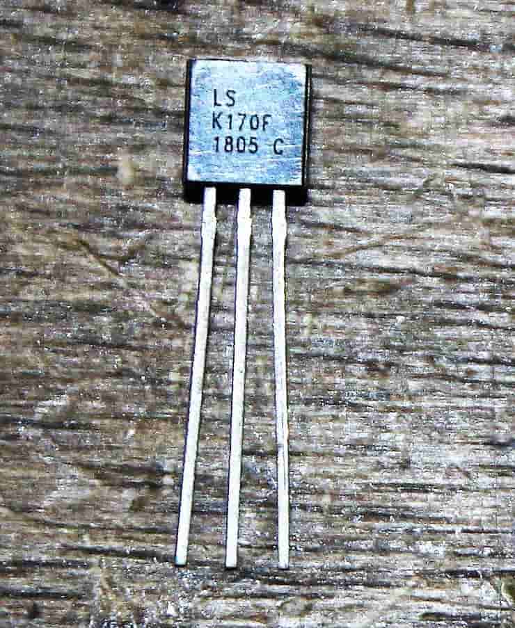
Low Noise JFet
Linear Systems
Such an old sweetheart "renew"? Does that make sense?
The XOno phono preamplifier was first introduced to the public in 1984. It developed very fast to the darling of the high-end hifi journalists (if I may write like that) and has been in not a few redactions later used as reference.
Shouldn't this old technology be outdated long ago?
There are several ways for a phono preamplifier to reach its goal, but these have not changed until today. What has changed, is the offer of semiconductors. The 2SK170 from Toshiba, which is so important, has long since ceased to be is produced. Fortunately, the manufacturers already offer the corresponding semiconductors. You only have to use them and then want to pay.
Nelson Pass cascaded the low-noise 2SK170 in the input stage. This is still an adequate means of Target achievement. The background noise is so low that the resistance noise is already higher. An improvement is hardly possible here. The phase inversion stage is operated with a constant current source (CCS). The RIAA stage deviates is only slightly different from the ideal. The quality drops and rises with the capacitors used here. The DIYer can be used here with to achieve a lot with simple means. The driver stage also accesses the CCS technology. A push-pull output stage with MosFets as output driver in Class A technology. This is how modern tube amplifiers are still built today.
Theoretically one could start with the constant current sources driven by the red LED. Even the oversized Mosfets were exchanged for others. But the technology remains.
And if you hear this preamp, you know why it's NOT out. So I say yes to the technology and the renewal of the XOno!
alterations
And what bothers you now? What exactly should be changed?
The usability is unfortunately absolutely outdated. That our so precious audio signal by DIP switches has already disturbed me during the first study of the circuit diagram.
The Ur-Ono had to be opened to switch. The corresponding settings could be changed to a multi-page Take list.
Modern audio components today use microprocessors that realize switching operations via relays. The display information is passed on to the consumer via coloured displays.
This is where I'm going to start. More than a decade ago I already build a preamplifier from the magazine Elektor. A microprocessor (MP or MC for short ) was also used here to switch inputs and to set the level via a digital to regulate the potentiometer. Relays with gold-plated contacts were already used at that time. These relays are easily available and high quality.
The newer phono preamplifiers from Pass Labs (as well as other manufacturers) now use all of these Technology. The electronics of the MP are completely separated electrically from the audio electronics.
All objections removed? So let's go.
engineering
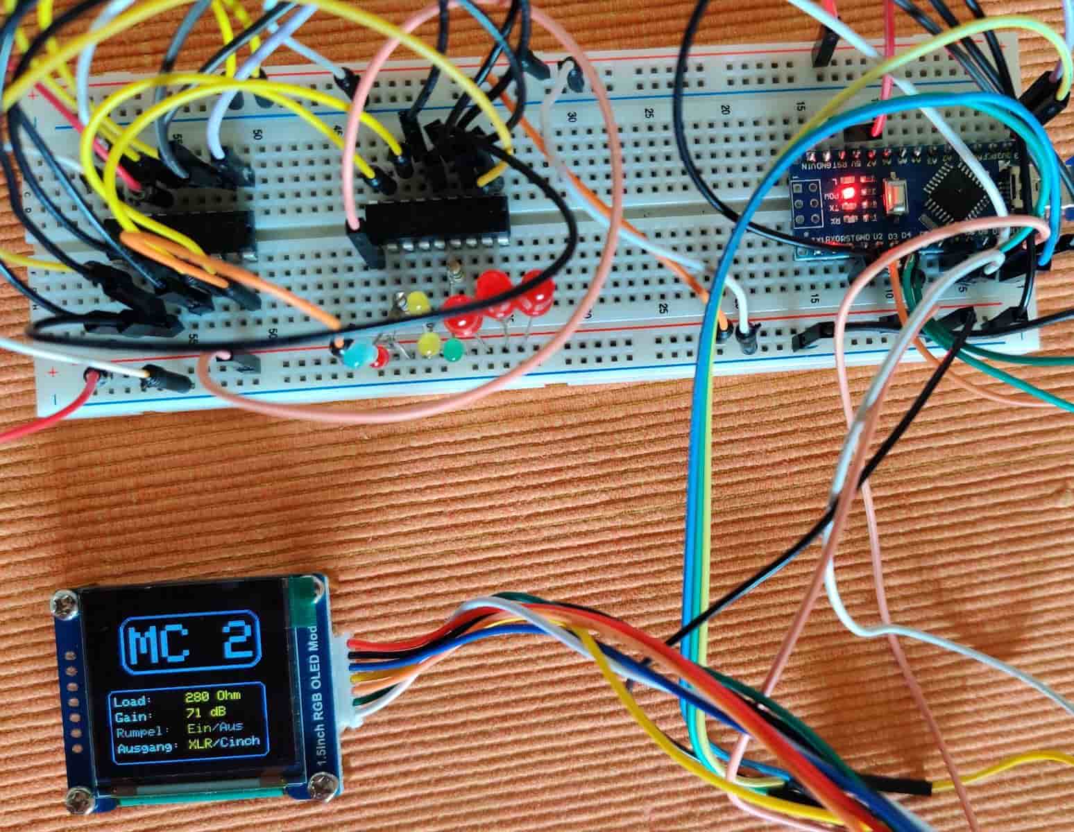
Microprocessor in test setup
How is this supposed to happen?
For those who have no programming experience, here is a short explanation:
I was talking about these microprocessors (MP), which are mini-computers on which a software expires. They collect data via sensors, control electrical processes and output data via displays. Let them these MPs simply network with each other. Today we find this MP in our entire environment. In a modern car more than 100 of these processors are in use today. The size is in the smaller IC range. With little external circuitry, complex solutions can be realized.
With it the way is chosen. In a nutshell:
- All switching operations of the DIP switches are replaced by relays
- All jumpers will be replaced by relays
- The control is carried out by a rotary encoder
- The settings are output in real time via a display
- The control is taken over by an MP
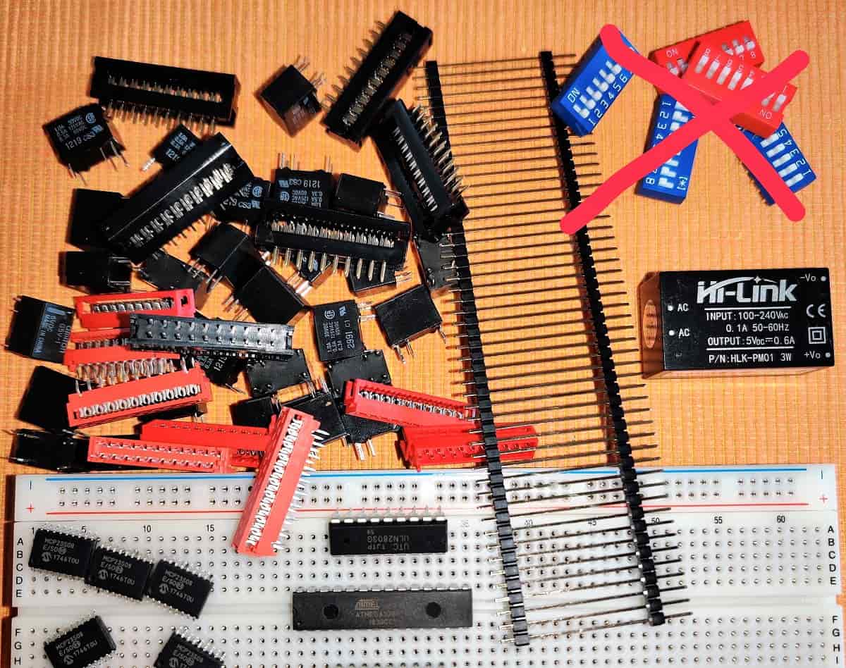
Component selection:
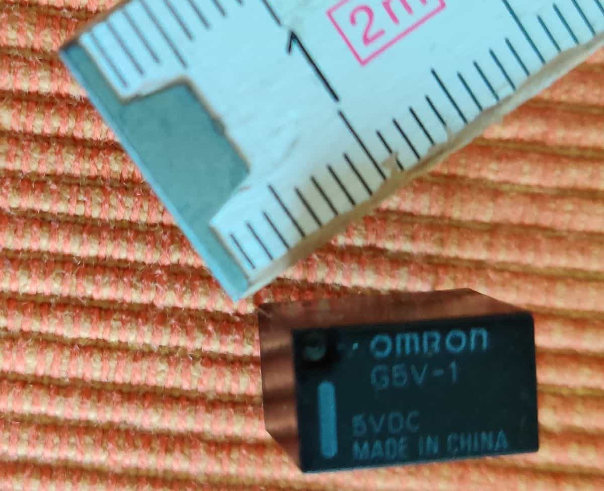
Relays G5V-1
Only types with gold-plated contacts can be used as relays. We only need them for an input or output. Switch-off process. So no multiple or change-over contacts. The size should of course be as small as possible. Power dissipation as low as possible. I chose 5V as the supply voltage, because the MP I preferred is also operating with this voltage.
My choice was the Omron G5V-1, 5V, 150mW, 1xOn.
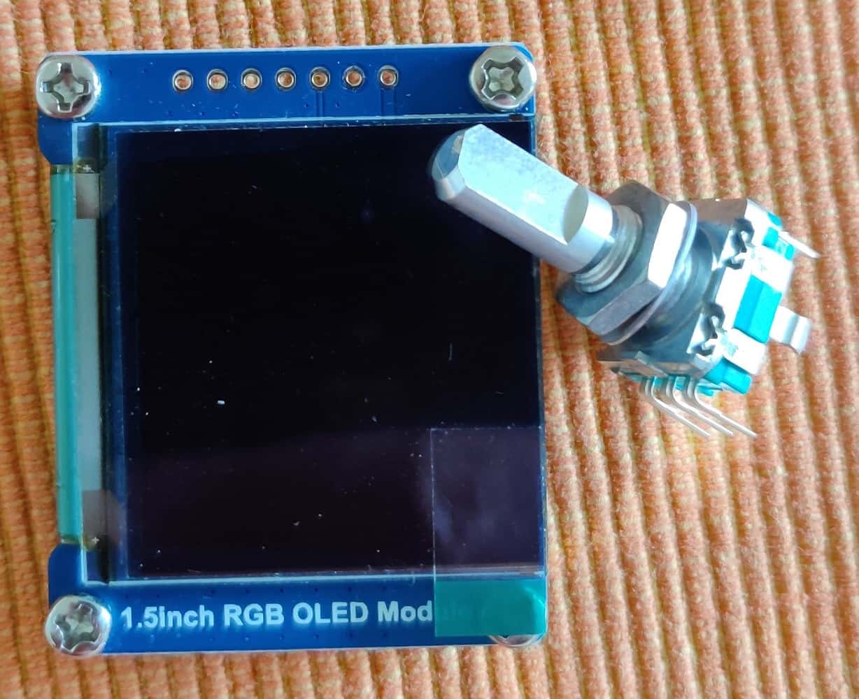
Display and rotary encoder
We get the rotary encoder (the actual name of these things is incremental encoder) from the company Alps. There are variants with thread. We must be able to screw this part into the front panel.
In view of the power consumption, an Oled in 1.5 inch size was selected. Because a colored display only is significantly more expensive and contributes to better visualization, this will be an RGB type with 64k colors.
As microprocessor I use an Atmega 328p in the DIP version. I have made this choice, because it has plenty of inputs and outputs and is inexpensive. It is an 8bit processor with a clock frequency of 20MHZ and has 32k internal memory.
These prerequisites are indeed met by many MPs. However, this can be programmed on the popular Arduino platform. Since I have worked with it many times before, it has been given preference. So I can accelerate the software development considerably.
With this we have almost put the additional hardware together. As power supply additionally an encapsulated switching power supply is used. This provides 5V/1A. That should be enough. In addition we still need various connecting cables, plugs, etc. and jacks. I'll get to that later.
Development:
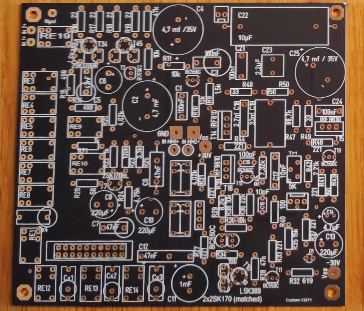
Come to the circuit board. DIP switches out, relays in. There are already 12 of them. Here I intervene immediately. We don't need 256 adjustment possibilities for the load adjustment. As with the XP25 I decided for 6 load resistors. This results in 64 setting options. We can handle this very well. Of course, the parallel 47k resistor remains unchanged after switching off all additional resistors.
I changed the capacity setting for the MM area as follows. The 1kOhm resistor was deleted. That's what I decided to do, 4 capacitors (47, 100, 180 and 330pf). This gives us a finer adjustment possibility.
We also need 2 relays to adjust the gain. And there were also the inputs. Another relay for two MC inputs. Same right for all: one more for MM. Switching between MC and MM also costs a relay.
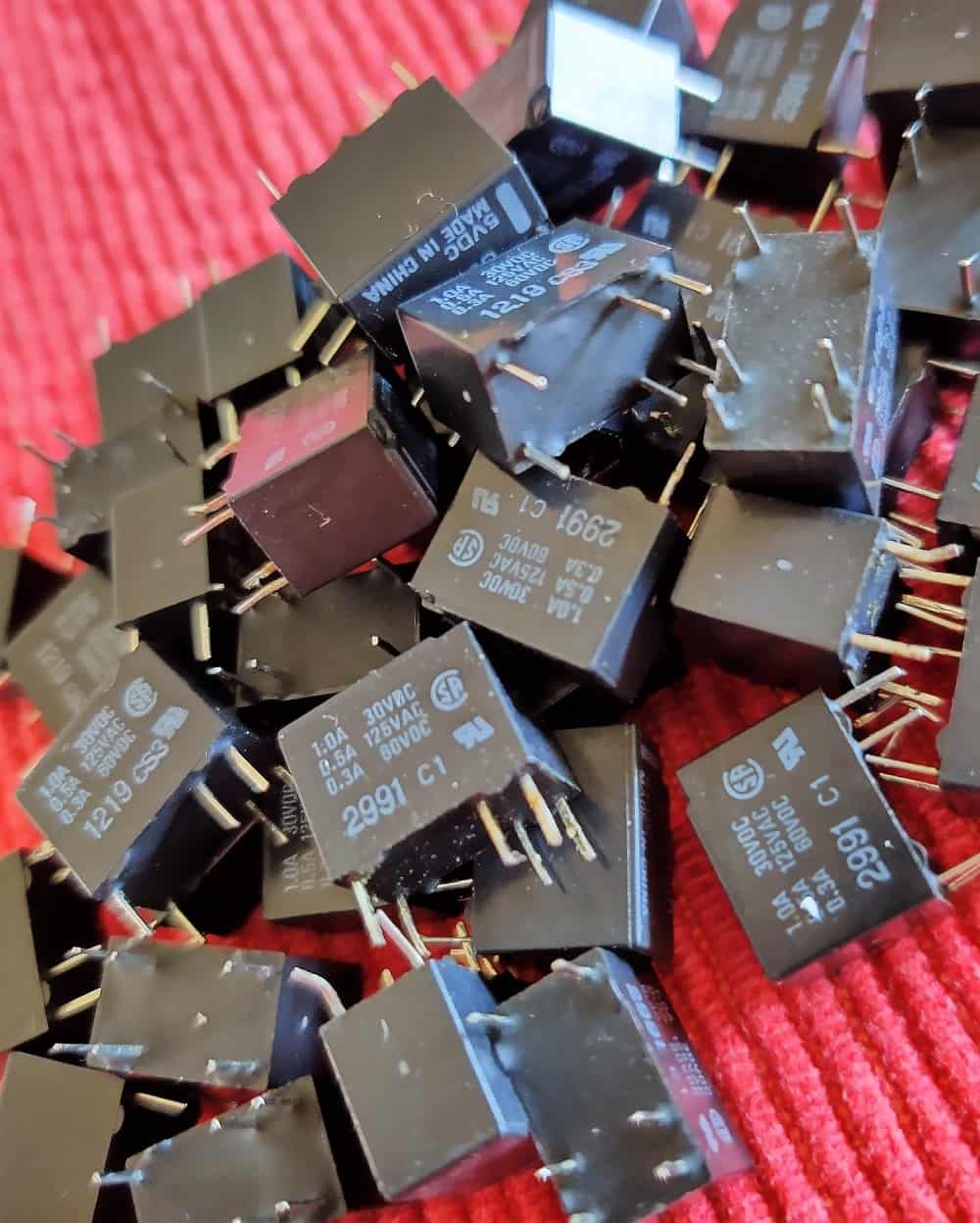
Relay Grave
Phew, this is gonna be a relay grave. There's something else. Switching XLR/Cinch. But you can also neglect it. What we do not want however in any case are noises when switching. So we need the possibility to short-circuit the output.
And a rumble filter. I want a rumble filter. Of course it can be switched off, by relay.
This results in a total of 18 pieces pretty exactly, for two channels 36 of these small switch cabinets. But we don't want any Microprocessor or peripherals on our audio board. So we add a 20-pin connector.
new circuit board
So, the (it didn't work that fast) board developed and sent to the realm of the rising sun.
Have you noticed? Something is missing.
A piggyback board holds the XLR part. The rumble filter also found a place here.
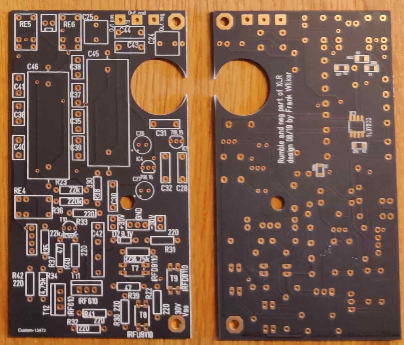
piggyback board
Further information about the filter can be found in the section Assembly and Commissioning. The output is also located on this part of the board. This board is soldered to the main board with three post connectors. Two metal spacer bolts complete the then very stable sandwich construction. Through a hole in the upper circuit board the trimmer for setting the quiescent current can easily be reached.
While the Chinese are ploughing, I will briefly explain how we perform these switching operations. Our MP has 28 pins, but of course it can't switch 36 relays. For this purpose we use a so-called port extension. This extension can be addressed via a changeable address and then switch 8 ports (here relays). The port extension is addressed via SPI bus and a select pin. With a select pin, 4 of these chips can always be addressed. Since the relays on both channels can be addressed in parallel, we need two of the extensions. So we get by with 4 connections. We will address the remaining relays directly with the MP. Unfortunately our MP and the port extension cannot drive the relays directly. The performance of these components is too low. With 8 relays we get at least 1.2W. So we need another component, to drive the relays. Of course, we could also simply use single transistors. However, the solution I have chosen is more elegant. The ULN2803 can switch 500mA at 8 channels per channel. A free-wheeling diode is also built in. In this case the load is switched to GND. That means, we put the supply voltage on the circuit board to the relay. The rest is done by our power driver. The remaining two relays are driven by single transistors.
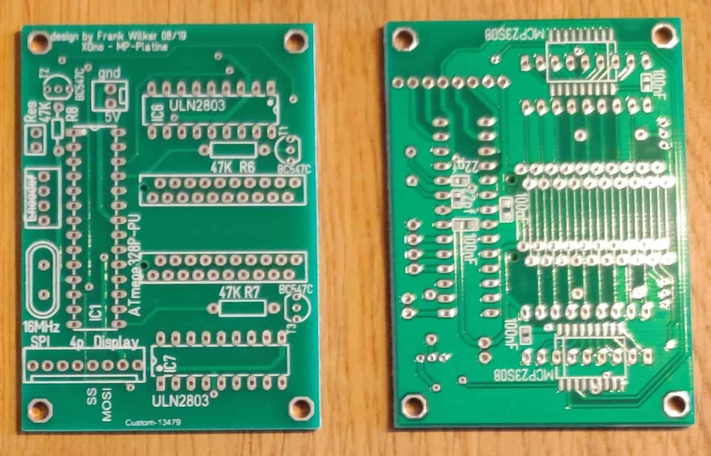
Microprocessor board
Our switch (rotary encoder) controls the selection of the settings via software. In addition, this rotary encoder has a button. All settings can be changed by programming the appropriate button without any problems.
Our display is also connected to the SPI bus. There is also a select pin here, so that port extension and Display always know exactly who is meant when the MP passes a command over the SPI bus.
Software and operation
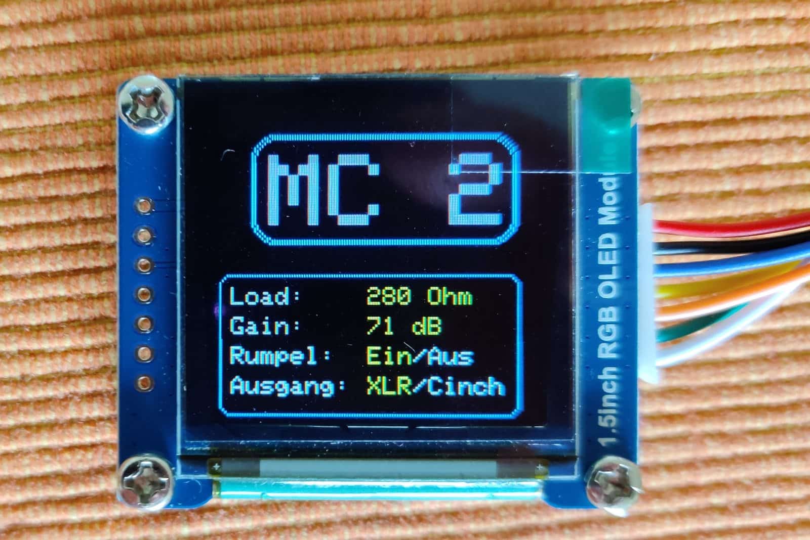
Display
1st attempt view
In fact, a large part of the software, namely the graphical user interface, has already been created.
For programming: When switching on, the MP switches all relays so that the output is disabled. Now the previously stored settings are read out from the internal memory and checked. If the Values conclusive, they are transferred. Otherwise, these values are overwritten by standard settings. These settings are now transferred to the relays. The preamplifier now gets a few seconds left. Time to warm up. The MP then releases the output relays. The display now shows the set values of the current input.
The rotary encoder can be used to recall the settings. There are the following possibilities:
- Turn clockwise - Adjust the load of the current input
- Turn left - Set the gain of the current input (only possible with MC)
- Press the encoder button briefly - Select a new input
- press the encoder button long - Opens the "Settings" menu
I have tried to make the settings as intuitive as possible. I think that a manual does not will be necessary. Some settings are also explained. These can be switched off in the menu.
equipment and commissioning
The waiting has come to an end. The boards have arrived.
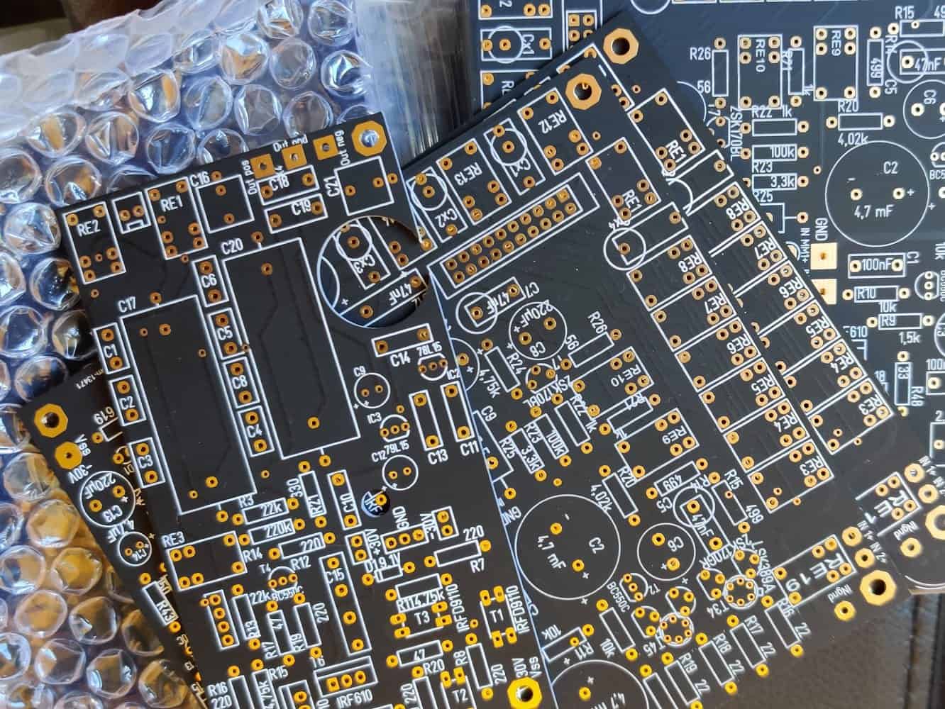
Boards
gold plated
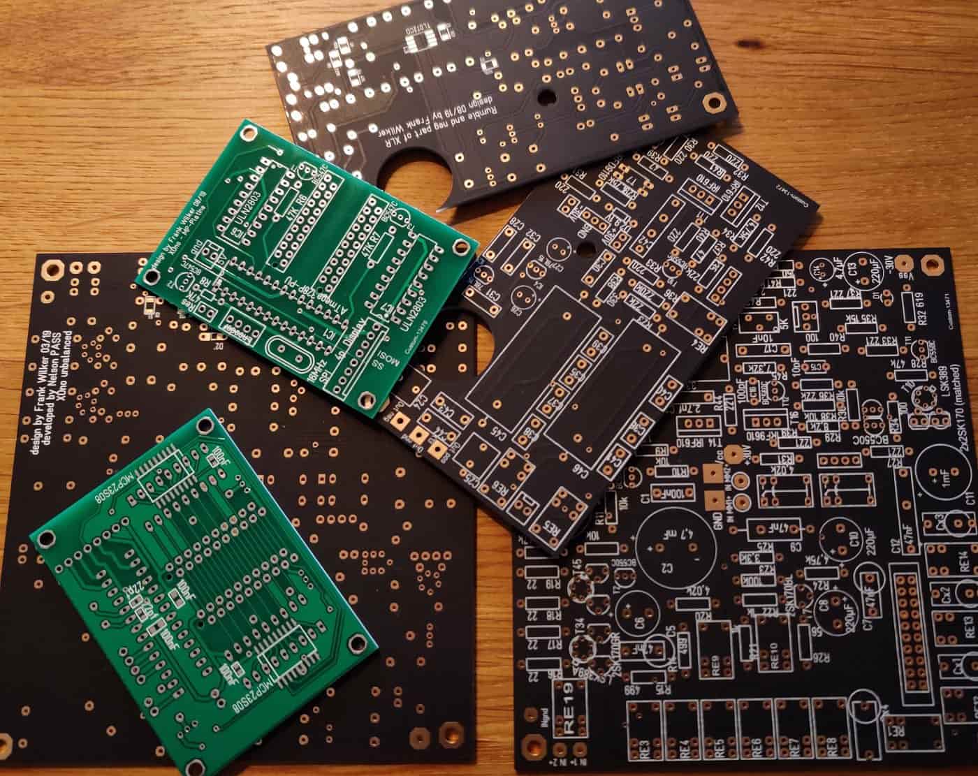
the whole package
incl. MP board
During the waiting time I have programmed the software further. It is now necessary to test whether all settings have been properly can be passed on to the relays.
After this, the functionality of the actual preamplifier must be checked. Since I took the layout from previous board developments, I don't expect any surprises here. There should be a maximum some swapped identifiers are causing trouble.
Finally, it would be the rumble filter. Does the cut-off frequency of 20 Hz correspond to the actual conditions? Does it function properly?
Tests:
To check the relays and their proper function I solder all relays and the 20-pin connector to the PCB.
Now it's the microprocessor board. Of course it has to be completely equipped for testing. The MP receives a socket, so that a change is possible without problems. This allows the software to be updated without any problems. There is already the first problem. The connectors to the circuit boards are reversed. A check of the board software shows that I did everything right, but the component is simply does not match the connectors ordered. If I order printed circuit boards again, I will simply mirror the components. At the moment I help myself with soldering the connectors from below. During the later handling of the circuit board according to I don't think the solution is so bad when it comes to making the connection to the motherboard. I'll just do it in the keep an eye. At the same time, I am also considering this possibility for the skin board; Simply use the connectors of solder in at the bottom. But then a separation is no longer possible after installation. Is that important?
We continue with the assembly of the MP board. The next trouble. After soldering in the ULN2803, the pins are in accordance with cut it out so far that the SMD chip 23S08, overlapping from below, bobbles so to speak. A narrower cutting of the Pins combined with a slight bending of the pins of the SMD chip also brings improvement here. The chip can be perfectly solder in.
So far so good. I programmed the first microprocessor in an Arduino Uno R3. I take it now and set it into the socket on the MP board. Plug in the display and the rotary encoder, connect the switching power supply and off you go. The display shows the basic settings correctly. The rotary encoder triggers the corresponding reactions when actuated. However, the outputs of the ULN2803 do not react during a switching operation. The solution is found quickly: I have forgotten, two lines of the SPI bus so that the two 23S08 are not addressed in the first place. Two short pieces of wire make the desired connection. Already the port extensions and drivers start their service.
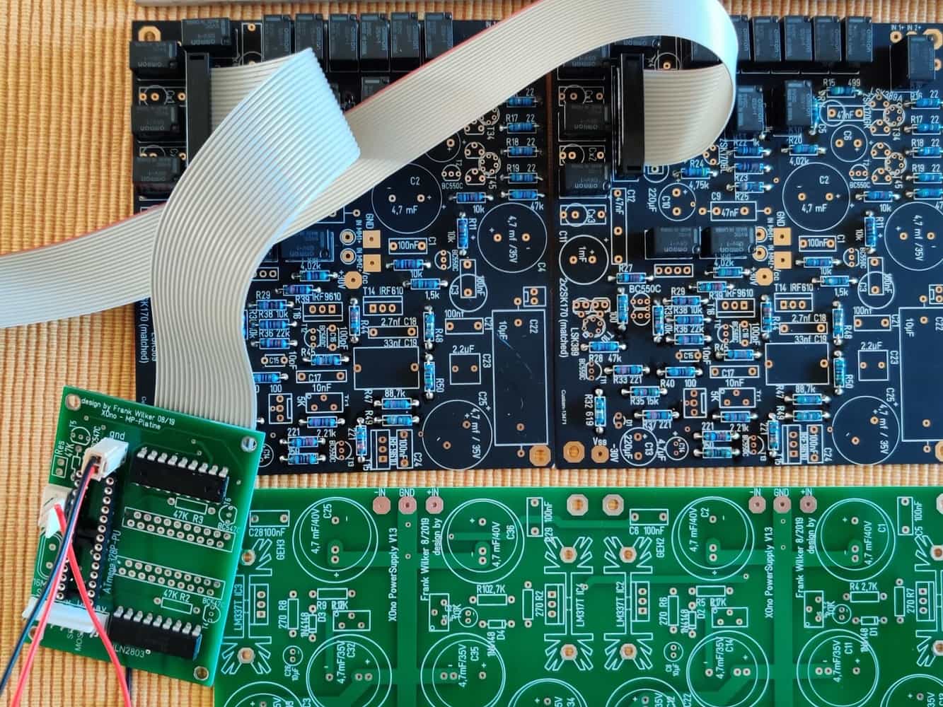
mp board
connection to mainboard
I now connect to the motherboard. It is important to squeeze the ribbon cable correctly into the connector.. The next test causes the first relays to click. Since it is too cumbersome for me, to test the function of each relay with a multimeter, I solder light emitting diodes parallel to the excitation winding of the relays. This allows me a immediately check. All relays are ready to function. Only one relay is weak. The quickly found fault is caused by an unconnected pin (solder joint). This error is also corrected quickly. Still the two relays that are switched by the individual transistors; that's it. Everything works.
Now I have to add the values corresponding to the relays to the software.
The software exam
Now this test has lasted for several weeks. There are all sorts of traps, which may surprise you. Since it is too cumbersome for me, the function of each relay with with a multimeter, I solder light emitting diodes parallel to the excitation winding of the relays. This allows me to immediately check. All relays are ready to function. Only one relay is weak. The quickly found fault is caused by an unconnected pin (solder joint). This error is also corrected quickly. Still the two relays that are switched by the individual transistors; that's it. Everything works.
Now I have to add the values corresponding to the relays to the software.
The software exam
Now this test has lasted for several weeks. There are all sorts of traps, which may surprise you. prepare. But after many hours of compiling and testing, the settings match the switching operations.
Now the real operation is still missing. In the course of the next few weeks it will also become clear to what extent the software is still worthy of improvement, or poor. The key question is: Is the software as intuitive as I imagined it to be?
Renovatio
fully loaded
XLR and rumble filter
fully loaded
Sandwich
well occupied
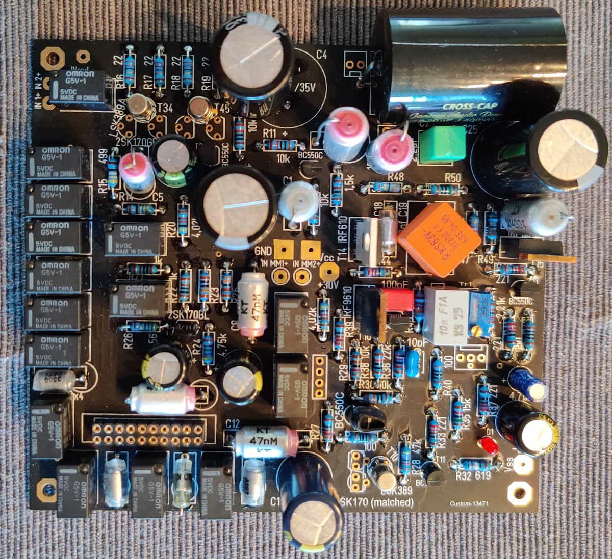
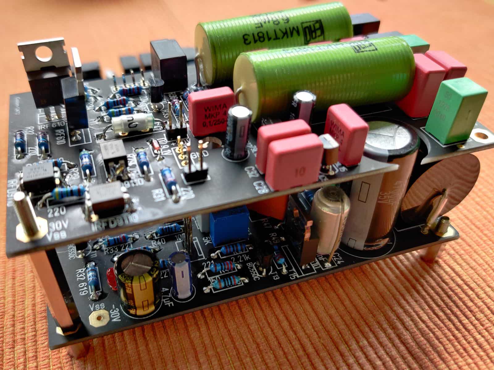
The assembly is the same as before: Assemble the components from low to high according to their height. SMD components are soldered first. After that we continue with the leaded resistors. Now the film capacitors and the polystyrene capacitors are added. On the shown circuit board I've also fitted the bypass capacitors in Poystyrol. These are after Teflon capacitors the qualitatively best capacitors that can be used in signal processing. Of course, unbelievers may also use foil capacitors. Now use the transistors (I used the LSK 389A I prefer), the LED and the MosFets. Now check the electrolytic capacitors, the output C and then the polarity of the electrolytic capacitors and the installation direction of the MosFets. Treat yourself the two minutes. That's better than desoldering and re-equipping. Another mistake is revealed here. The holes for the output capacitor (as well as C45 and C46) are too small in diameter. So take out the cordless screwdriver and rework it. In addition, the dimensions on the board are too small. This was not the case in my layout. There will be a note about this later.
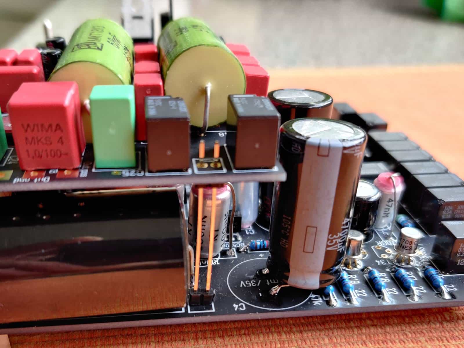
Sandwich
shifted capacitor
With the piggyback board I proceed in the same order. Here too I find two errors immediately. Two resistors are misnamed. That smells like post-processing. After everything is assembled, I put the boards together for a test. Too bad, C4 is too high and bumps against the upper board. Here I help myself by connecting the wires a little longer. and then turn left. You can see that at the top. The stud in the upper right corner is also out of place. The space for the capacitors is simply too small. But since the whole construction is already very stable without soldering and the XLR connection will also be established in this area later, I'm not worried. I'll just leave it out for now.
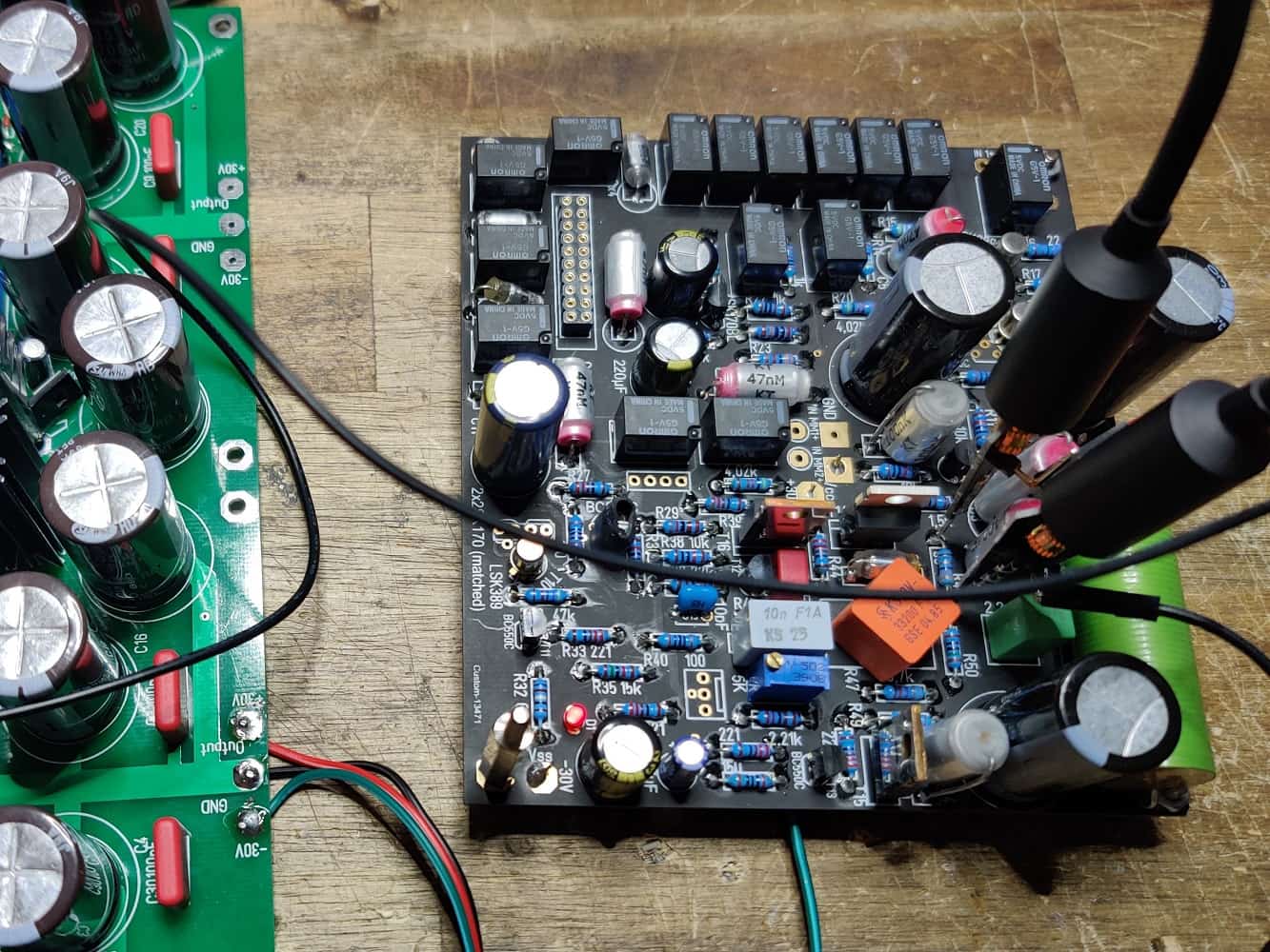
Prüfaufbau
Now the electrical test is pending. Power supply unit connected, switched on and the LED starts working. The previously attached measuring terminals show a voltage increase up to about 300mV. Before I finally adjust the quiescent current, I adjust the operating voltage exactly to +/- 29.5 Volt. Then I measure the quiescent current again. This current is still below the required 350mV. Now the constant current sources (CSS) are on. CSS1 shows a voltage drop over R32 (in my case 619 Ohm) of more than 1.4 Volt. That means a quiescent current of 2.3 mA. More than 10 percent too high. With my other setups I almost always hit exactly the 2.1 mA with a resistance of 619 Ohm. Now I have to recalculate: R = U/I 1.43V / 2.1mA is almost exactly 680 Ohms. So I exchanged the 619 Ohm against 680 Ohm and the CSS now allows almost exactly 2.1mA flow.
Let's go to power source 2. To do this, we measure the voltage drop across R43. In the original circuit diagram 150 Ohm are used here. I usually use 200 Ohm to get the required 6.7mA. My measurement yields a current of 6.75mA. This deviation I tolerate.
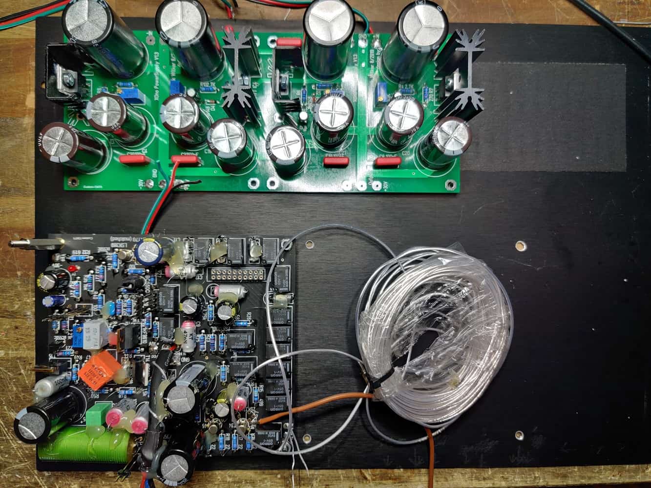
Well, I'm resetting the quiescent current. After the circuit has been running for half an hour and the quiescent current (350mV over R48) isn´t changing, I'm turning it off. After I have finished the 2nd board as well, I start building the case.
A little hint
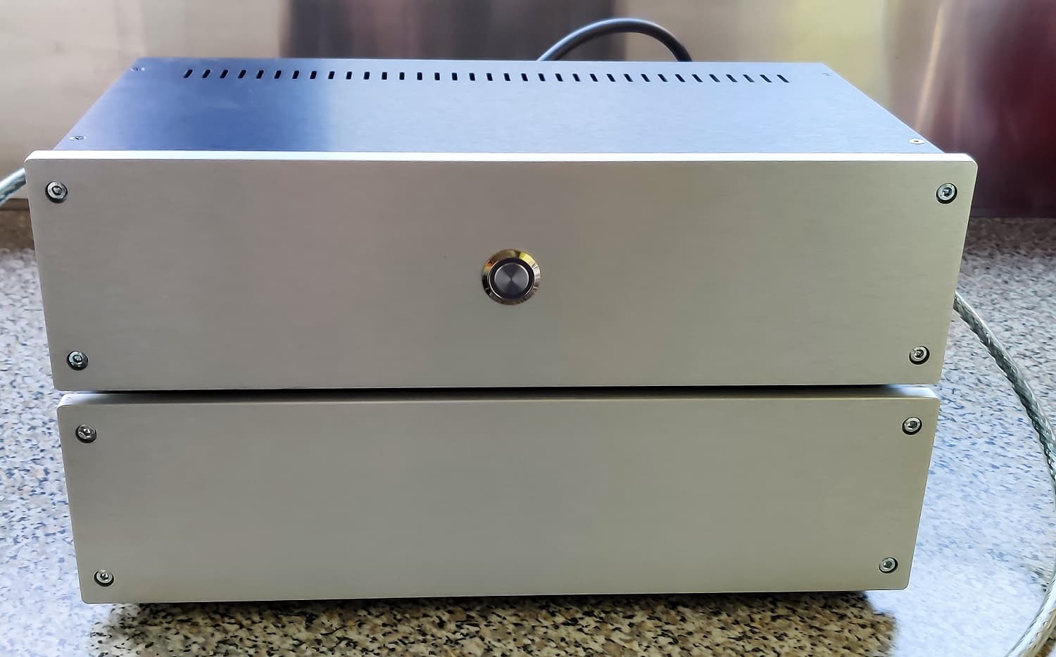
Gehäusebau
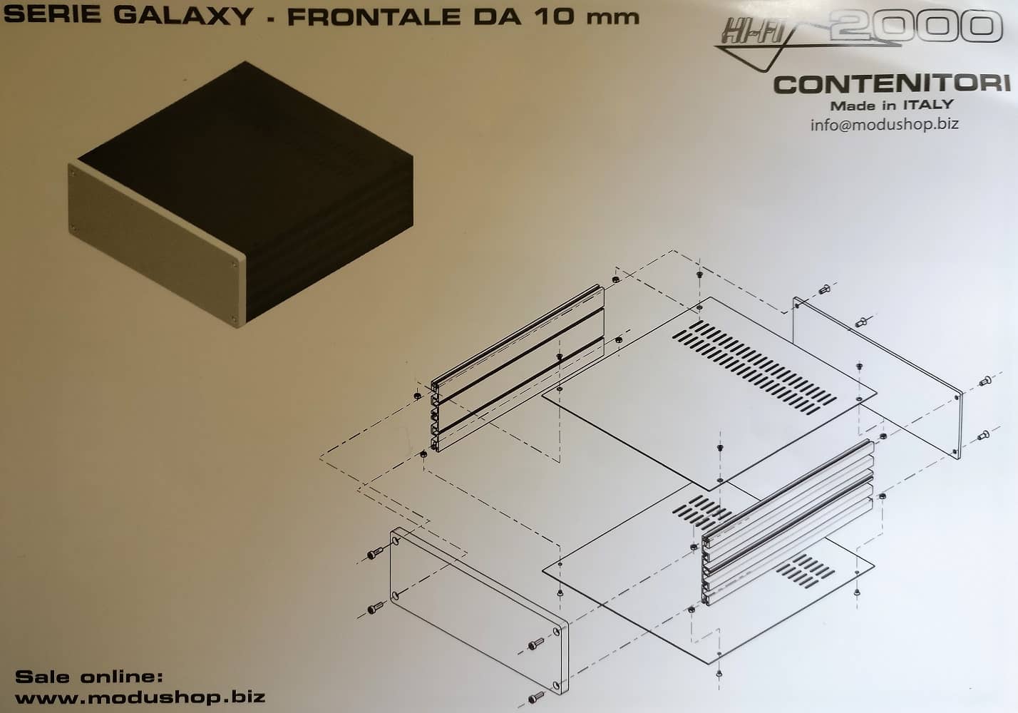
Galaxy Maggiorato GX383
2 Height units
Also here I use again a case of the company Modusshop from Italy. These are available in various dimensions and variations. The dispatch is very fast. If you order there, you will have the cases after three days at the latest lying at home.
I use again the Galaxy Maggiorato GX383 case; 330 x 220 x 80mm. Since I still have one of these aluminium cases at home, it is used here as a prototype. As already mentioned on the XOno project page, I only order Housing with powder-coated base and cover plates. In the meantime I also take the black front because of the fast soiling only reluctantly to the housing construction.
bottom plate
and back
Einbau
der Platinen
piggyback
board installed
I'll proceed as follows:
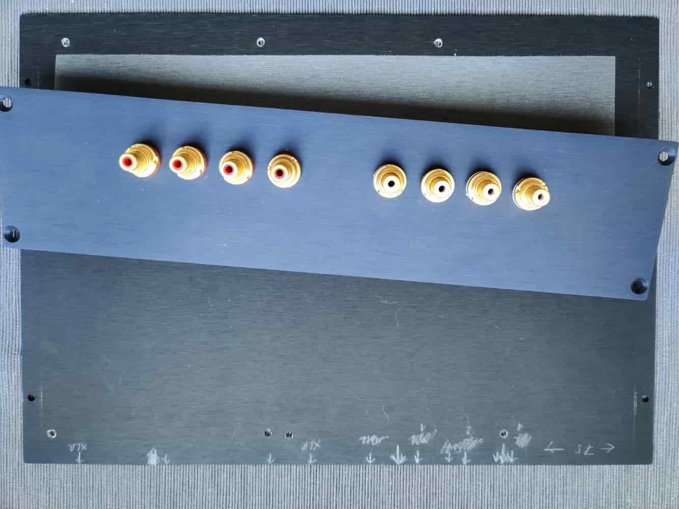
Drill the holes in the base plate to fix all boards. Then I measure where the cinch sockets and all further outbreaks in the back should be given their place. With eight input sockets for four inputs not quite simple. In addition, the space above the piggyback board to accommodate the XLR output jack is rather small dimensioned. I will not measure this hole until the boards are installed. I will proceed in exactly the same way with the installation of the power supply socket.
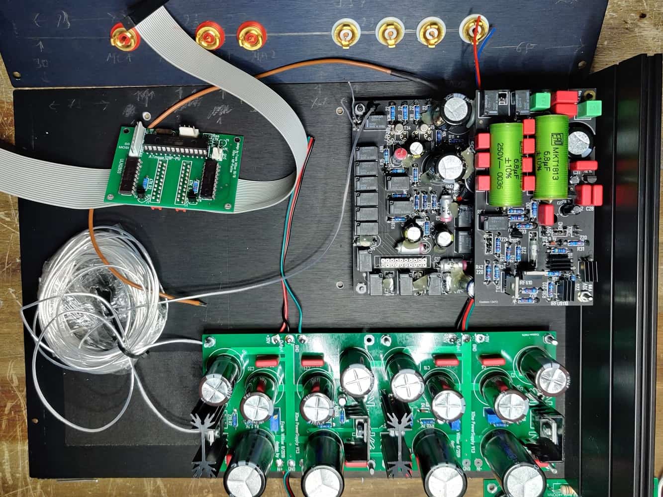
I provide the power supply board with the necessary connections and install them first. Then follows the one on Main board located on the side panel. Before I screw this on, I solder the input cables for the four inputs already on the circuit board. Because the cable for the MM inputs is a little bit longer, I use here a shielded double wire Cable. I use the two inner conductors for input MM one and two. I extend the shielding and connect them from inside with the body screw. To connect GND, an additional cable (silver, teflon insulated) is connected several times around the shielded cables wound. The whole is then fixed with some hot glue. While I'm at it, I'm fixing also all capacitors on the board. For the two MC inputs I use a non-shielded cable. The cable length is about 3cm, so that shielding is not necessary. Now the main board is connected with a distance of about 10 to 15 millimetres away from the rear wall. Here I realize later that a greater distance gives me more freedom when placing the XLR output socket. I try to place the housing screw, which is accessible from the outside first centered above the cinch sockets
Now install the piggyback board and take a look at the whole story first. After measuring the remaining gaps on the rear panel, I decide to install the XLR socket rotated by 90 degrees. The cinch socket finds about 30mm next to it, his place.
TIPP
If you do not need a balanced connector, you can of course simply leave out the XLR socket. In this case the XLR part needs on the piggyback board are of course not assembled. If the board is already populated, this part can be pulled through of the jumpers located on the board can be simply switched off. I have developed this possibility with regard to my in development of a rechargeable battery power supply unit. This way the power consumption can be minimized.
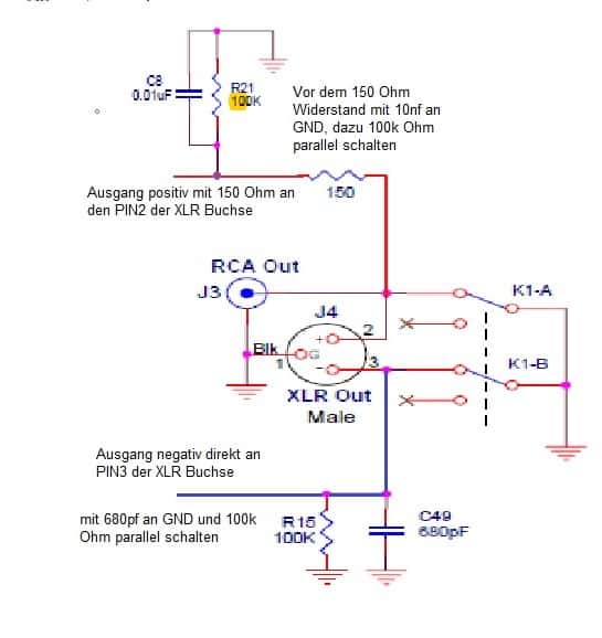
XLR out
circuit
Now I prepare the connection to the outputs. The negative output gets a 680pf capacitor connected to GND. In addition a 100 kOhm resistor is soldered in parallel. The positive side is connected via a 150 Ohm resistor. A 10nf capacitor and also a 100 kOhm resistor is connected to the negative side. But here the connection is made BEFORE the 150 Ohm resistor! Also here I solder corresponding cables.
The connection to the inputs and outputs is established when all boards are installed and wired.
After installing the second sandwich construction, the last board to be installed is the head of the whole story: the microprocessor board. The pictures speak for themselves and spare me further explanations. It is already clear to me today that the next board will have turned connections to the amplifier boards. I will lay these cables underneath the boards the boards. The 20-pin ribbon cable has to be bent only once to connect exactly with the PCB connector, which I will then which I will also place underneath the amplifier boards. The necessity to be able to remove this cable again I can not see the need to remove this cable.
Lumberg
5-pol ps connection
Now the power is still missing. The power supply plug gets its place at the back left (seen from the front). Since I usually work with only one balanced power supply (+/- 38V), I use a five-pin plug/socket. With the socket the plug version has to be used. So the counterpart at the cable end of the power supply consists of the female version. So you cannot to the contacts by mistake and provoke a short circuit. Meanwhile I use for the power supply I always use a plug with a molded cable. This is a bit more expensive, but has the advantage of saving a lot of time. Anyone who has ever assembled such a cable knows what I'm talking about.
I use the plugs and sockets from the company Lutronik. The quality is very good. And there are hardly any alternatives in terms of price. The plugs and sockets are also available in an 8-pin version, if the PreAmp is mounted fully balanced.
Lumberg
connector
After installing the connector, I connect the cables to the boards. The power supply gets three solder connections; The MP board gets one connector. Please note the polarity.
This is almost the final step. Just solder the cables of the input and output sockets and screw the rear plate to the side parts that have been inserted in the meantime.
Final means that last but not least the front panel has to be installed. Now the display and the rotary encoder have to be in such a way that both components can be seen and operated reasonably. At the same time they must not must not collide with the power supply board behind it.
For this purpose, I have gone through several possibilities:
- Front panel from Modusshop in 3mm aluminum
- Front panel from Modusshop in 10mm aluminum
- Ordering a front panel from the Schaeffer company
- Glass front rear painted and drilled
Now we come to the 3mm thick aluminum front panel. Here we can simply drill a hole and screw the rotary encoder there. screwed there. For the display we make a cutout that only shows the viewing area of the display. We fix the display with with hot glue (if you like it) so that the visible area is aligned with the cutout. Otherwise a correspondingly aluminum angle would also hold the display in place. If you want it to be really professional, you can insert a piece of acrylic glass into the cutout. This is by far the easiest solution for an appealing case design.
The 10mm front panel worries us a bit more. Due to its thickness, a cutout is not enough for the display. You would look at the display like through a tunnel. That would not be very attractive. It's exactly the same with the rotary encoder. It would then not be possible to screw it on. Only a little bit of the axis would stick out. So we need another another so-called flat surface behind the display and the encoder. This can be done by hand. However you need the right tool. To realize my ideas here, you need a CNC milling machine. This mills a 8mm deep plane (pocket) into the back of the front panel (behind the visible cutout). It is then only the active area of the display will be visible from the front. The display will disappear in this pocket.
The rotary encoder receives a round approx. 5mm deep flat surface on the back. The visible side of the front panel is also a 2mm deep round surface at the same position. Here we can easily disappear the rotary knob, with which the encoder later can easily disappear into the front panel. This looks noble and if we already have such a milling machine at the start If we already have such a milling machine at the start, this plane surface can easily be included in the milling program. This should have a diameter two millimeters larger diameter than the rotary knob. Within this plane surface we need another plane surface. This takes the nut with which the rotary encoder is screwed into the front panel. Otherwise a massive rotary knob would would protrude far beyond the front panel. The rotary encoder can then be inserted into the front panel from behind.
The 3rd option is unfortunately a bit more expensive. A front panel at the company Schaeffer with the under the 2. variant costs about 110€ at the time of writing this page. The 10mm thickness is only available unfortunately only in aluminum nature. If you want colored anodized or even chromated aluminum, the thickness can be a maximum of 4mm. You can also supply your own material. Then the financial cost is 53€ plus shipping there and back.
Now the glass front. Crazy, isn't it? Acrylic would also be a possibility, of course. By the way, there is also Schaeffer. Okay, the glass front. My glazier assured me that drilling is no problem. The pane will then have 4 to 5mm thickness have. The back will be painted black. The visible surface of the display will be masked (i.e. cut out). Here the display will be visible later. Display and encoder have to be glued together. There are enough glues, with which this can be done well.

Front panel
Fa. Schaeffer
Front panel
Glass back coated
Other
I was already thinking about the number of inputs while programming the software. What about the user who needs only one input? My first idea was to provide a setting option in the software. Since I used the memory of the MP to 80 percent, I prefer a hardware solution. I will provide slots on the MP board which I can use to select the inputs via jumpers. Then the software only needs to query the jumper position. to query.
Otherwise, some further developments would still be due:
- Revision of the constant current sources
- höhere Verstärkung
- more modern output stage
I have already thought through these developments several times. However, the execution is still in the distance.
Update
A long time has passed without any further development being documented here. The reason lies in my wrong conception. I did not succeed in completely immobilizing the device. Due to the high total power of the used relays used, there were clearly audible disturbances, which I could not control. Due to my cramped setup the troubleshooting was additionally additionally complicated. This resulted in a considerable expenditure of time, which made me rethink the whole concept. rethink.
Ultimately, this resulted in the following changes:
- Banishing the relays from the amplifier board
- Use of relays with lower power
- Print RCA jacks instead of wired RCA jacks
- The rumble filter has been deleted
The new concept means that the current motherboards of the XOno can be retained. As a consequence of this I developed add-on boards, which are placed in the rear part of the amplifier board. These contain the relays, Cinch sockets, as well as the corresponding connectors to the outputs and inputs, gain circuitry, etc.

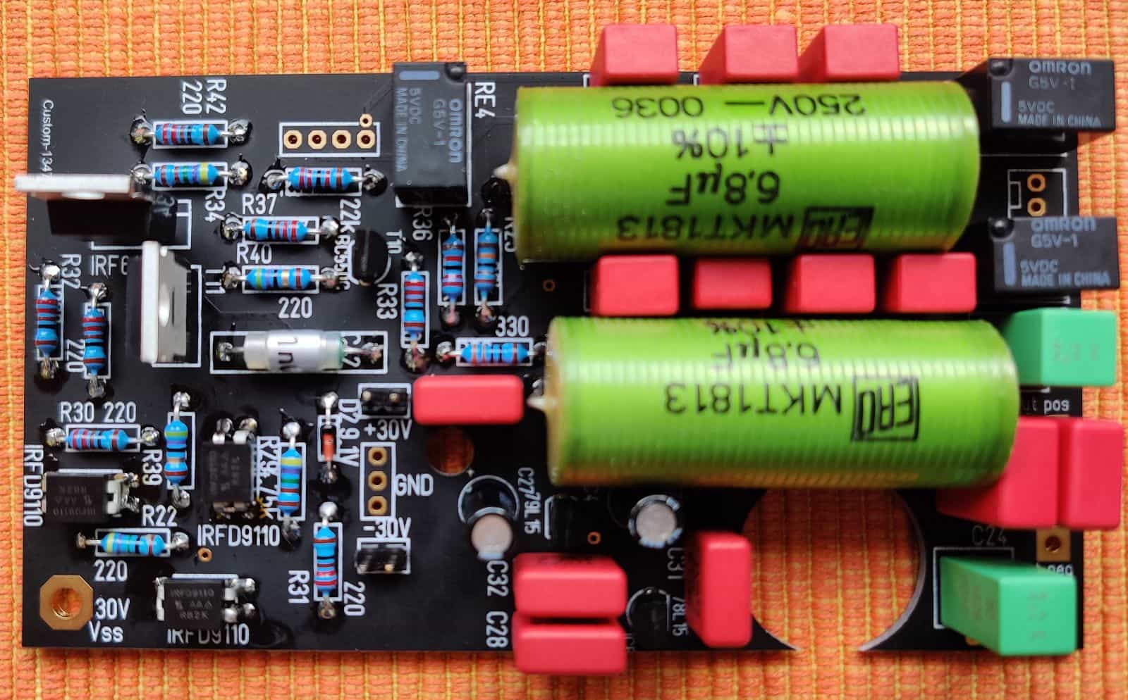
Attachment board
Relays and RCA sockets
Relay
50mW Power
RCA sockets
little mass
And now the trouble starts again. The holes for the measuring points for setting the quiescent current had not been milled. The hole for the trimmer; Unfortunately, somewhat inaccurate. Again too complicated thought. Why not place the board 5mm below the the main board? And solder the components from below. This way the mainboard is about 15mm higher, but this is not really problematic.
In the next few days, the board shown above will be provisionally connected and tested. If this test is positive the new boards will be ordered. In the meantime I have also worked on the software and optimized.
I am confident that this project will be completed soon.
Stay tuned
Downloads
Unfortunately, these are not yet available.