MC/MM Phono-PreAmp XOno
realized by Frank Wilker
last modification: 06.12.2019
- design by Nelson Pass/Wayne Colburn, developd for PASS Labs, introduced 1994 as Aleph Ono
- Infos auf diyAudio
From tubes to transistors?
In my search for circuit diagrams and information about high-quality phono preamplifiers, I often came across the name XOno (design by Wayne Colburn). Due to my tube addiction this was of course out of the question. Fortunately, this attitude changed during the "ONLY" years of my life.
It had long since become clear to me that semiconductors are excellent candidates for collaboration with tubes. So it was not a long way to a pure transistor phono preamplifier.
My first attempt was an IC preamplifier from Sjöström Audio. In principle, only the circuit diagram was taken from the data sheet and refined. This device worked perfectly without any effort, but did not throw me off my feet.
As so often I had very little time left and invested in a cheap device from Pro-Ject. The sound didn't differ from my self made, it looked more professional. So I took some more money into my hands.
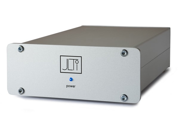
The JLTI
Vacuum State (Allen Wright)
Since Allen Wright had become my hero, I invested 600 € in a used transistor phono preamplifier from Vacuum State Electronics, the JLTI. Not much of an improvement either. Actually, I was a little disappointed. Especially since my components weren't exactly cheap.
Here the Roksan Xerxes 20plus already played with a Micro Benz Ruby Air III. I lost the desire and let it be good for now. Later Michael Methe's site inspired me to rebuild a Hiraga PrePre. In terms of sound, it was actually a step forward, but the power supply problem and the constant adjustment spoiled my fun.
When I had more time and energy again, it came to the construction of the "His Master's Noise". A well documented project from DIY-Audio. At the same time I bought input transformers from Sowter and felt on the safe side. Unfortunately there was again more hum than I liked.
Humm just sucks
The humming that occurs when a turntable is incorrectly connected to the phono amplifier can really get on your nerves. Sometimes it's just some little things that cause this impairment of pleasure.
In the past, I had always given up quickly if the hum wasn't to be repaired immediately. Meanwhile I have a bit more experience and know that with a bit of persistence you can eliminate any mistake. However, it's very interesting what's going on in this area.
But back to the subject. In fact, the hum was gone later when I built the transmitters into a sensible walk. But (fortunately) I only made this observation when the XOno construction was in full swing.
Meanwhile I had read a thread of XOno on DIY-Audio and intensively studied the side of Ralph Stens, RSTAudio. So I e-mailed Mr. Stens and asked him for circuit boards.
He was kind enough to point out to me what it was. Not a power amplifier, but a phono preamplifier. Well done and ordered. The circuit boards were there quickly and lay around a bit, since I had tackled the building of the housing of the sowter and the HMN.
What excited me the most was the reference to the XOno's complete freedom from hum. At that time I still thought that couldn't be. It will already hum a little. But I was actually taught better.
Do you know that when the journalist writes in the high-end magazines with the glossy high-resolution images: "Before I put on the needle, I thought I had chosen the wrong entrance. It was nothing to hear at all!"
That's exactly how it happened to me. I hadn't noticed into which input socket I had plugged in the cables and already turned up a bit louder. Apart from the barely perceptible hum of the tube-amp nothing was to be heard.
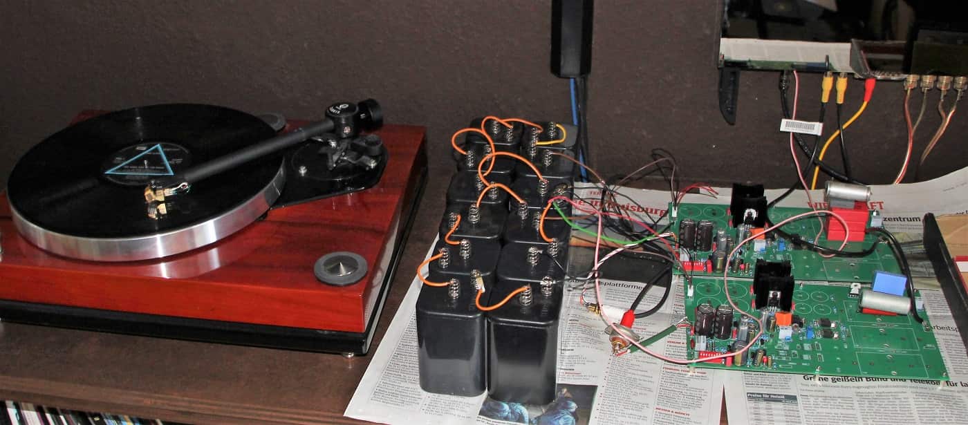
The RST-Boards
in battery mode
Until I put on the needle (now I'm already writing like that...). My wife immediately came around the corner and remarked whether I needed a hearing aid. To get to the point:
It wasn't a little hum to hear. And this, although I had provisionally provided the non-installed circuit board with the cheapest cables for testing and thus connected it to the system and amplifier. I also noticed a clear progress in sound quality.
The channel separation was immediately noticed. The finesse of the sound, I would call it that, stood out clearly. What I was missing at first was a little power. However, this was relativized later on.
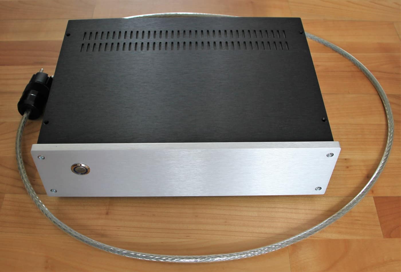
What I hadn't considered in all my madness was that I had operated the whole provisionally with batteries. These were still lying around with me and were quickly put together. Thus at least no net hum could enstehen.
In retrospect, I also had the idea again and again to cover the whole power supply with rechargeable batteries. But to produce 2 x 30V constantly from batteries means a lot of effort. However, the operation on the mains was so hum-free that I (for the time being) didn't think about a mains free power supply anymore.
Only MC part as transformer replacement
After these first positive impressions the decision was made. I studied the circuit diagram of Wayne Colburn and "just" made a circuit board. Off to China and wait.
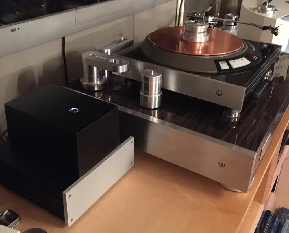
This is how it should look later (the housing is also available in black)
Now we have time and I can talk a little about the circuit boards. Normally I avoid placing intercontinental orders for any goods you can get at home for a little more money. Unfortunately, however, in this country you have to pay ten times or more for such a board. Especially prototypes are extremely expensive.
I also finished a power supply board right away. But at that time I had simply forgotten the power transformer. In the current version it is on the board. What I also hadn't considered was that a case would be quite nice (or what kind of case). After I found out that Hammond's slide-in housings could easily accommodate two PCBs, I chose them.
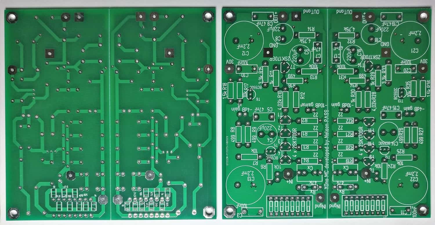
MC-Board
separate grounding
After five days, the sweethearts (circuit boards) are ready. Three more days I wait for the arrival. The quality is as always very good. I don't want to deny a few little mistakes. The designations for 2 resistances reversed and an electrolytic capacitor twisted. That's it. Actually a good result. Who has done something like this once, knows how difficult it is to get a faultless circuit board on the first try.
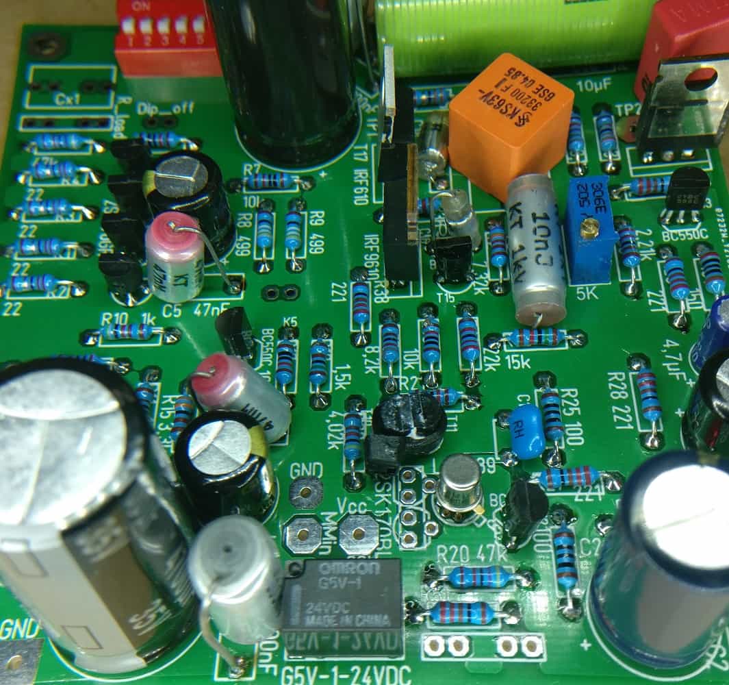
Now it's time to assemble. The components are mounted on the board from small to large: SMD resistors, leaded resistors, DIP switches, transistors, connectors (for the jumpers), foil capacitors and electrolytic capacitors.
The components placed at the edge touched the groove into which the circuit board is inserted. Since there have been a lot of requests and I needed more parts, I ordered another batch of PCBs. So both boards got a 6mm wide free edge, so that they now fit exactly into a slot.
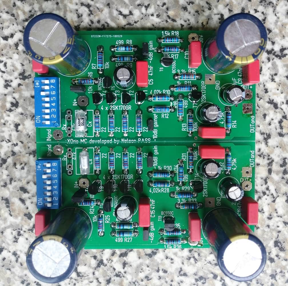
MC-Board
complete assembled
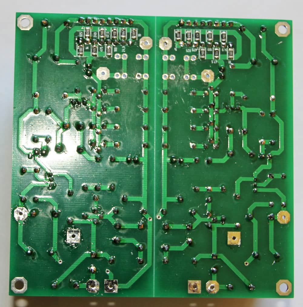
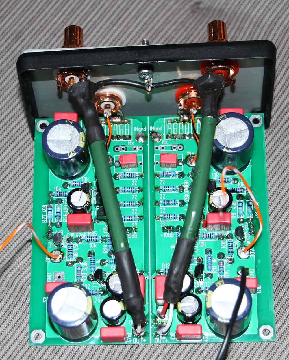
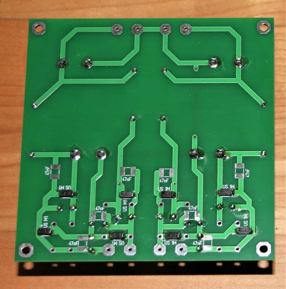
MC-Board
Bottom view
New Boards
with edge to insert
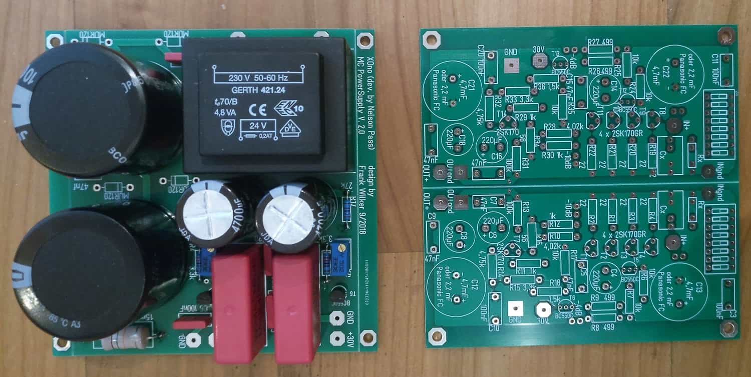
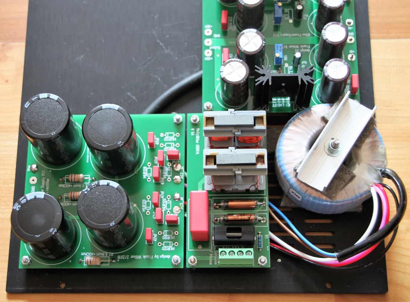
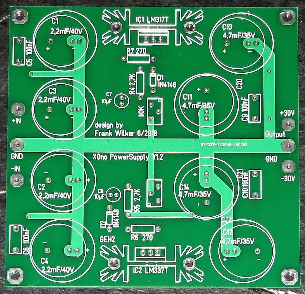
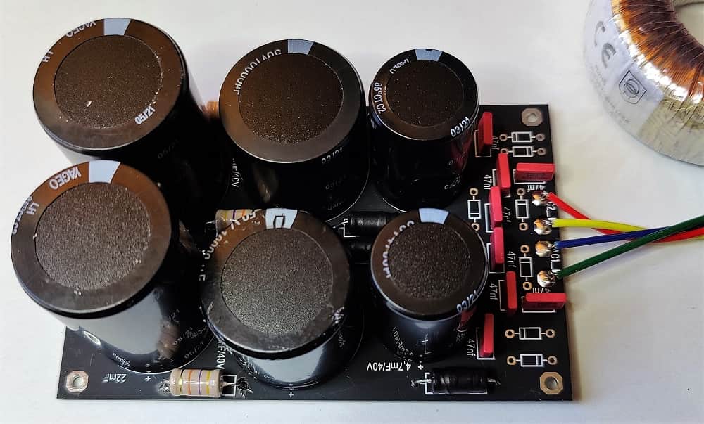
PSU XOno MC
Since the power supply board differs, even if only slightly, from the board used for the "big" XOno, there is a separate section here.
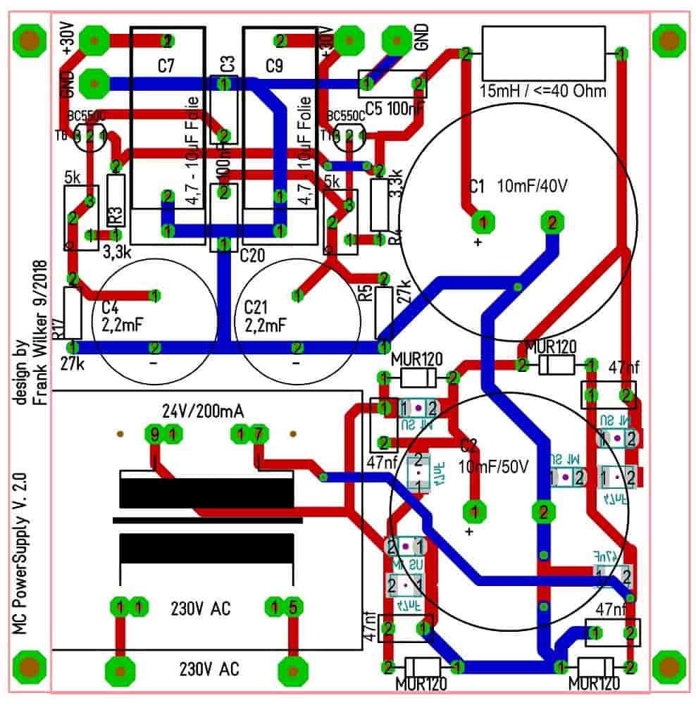
PSU
Transformer on Board
This board is also assembled as described above. The circuit consists of a CLC screen with subsequent capacitance multiplier. The sieving C serves the base of the output transistor and filters the output voltage.
This costs us a few volts. These are available as surplus anyway. The output of the power supply can be loaded with approx. 50mA per transistor. That's enough loosely. One channel of the XOno-MC preamplifier needs a maximum of 25mA.
For adjustment we need a load resistor. For 30 mA it does a 1k resistor. The resistor should be loadable with at least three watts, because with 30mA*30V we generate 900mW power dissipation.
For the first start-up I connect a power cable directly to the circuit board. After applying the voltage, the DC voltage slowly rises. With the trimmer, the desired voltage can be set relatively easily.
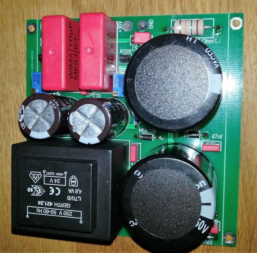
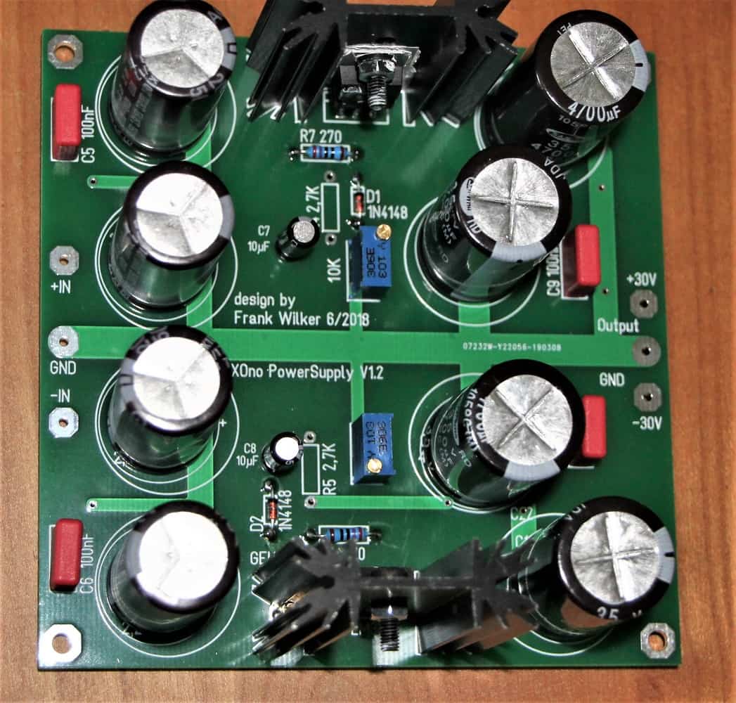
PSU
full mounted
Because of the large capacitance and the low required power, the voltage changes only slowly. So just make a few turns and wait. But you get the hang of it quickly. I now set to 30V and connect the circuit board.
In the original circuit Wayne Colburn connected the power supply via resistors (5.1Ohm/2W). The actual operating voltage is then 29.5V. I will adjust to this voltage later if the board is working properly.
The resistors that are probably used to limit the current in case of a defect are saved in the MC version.
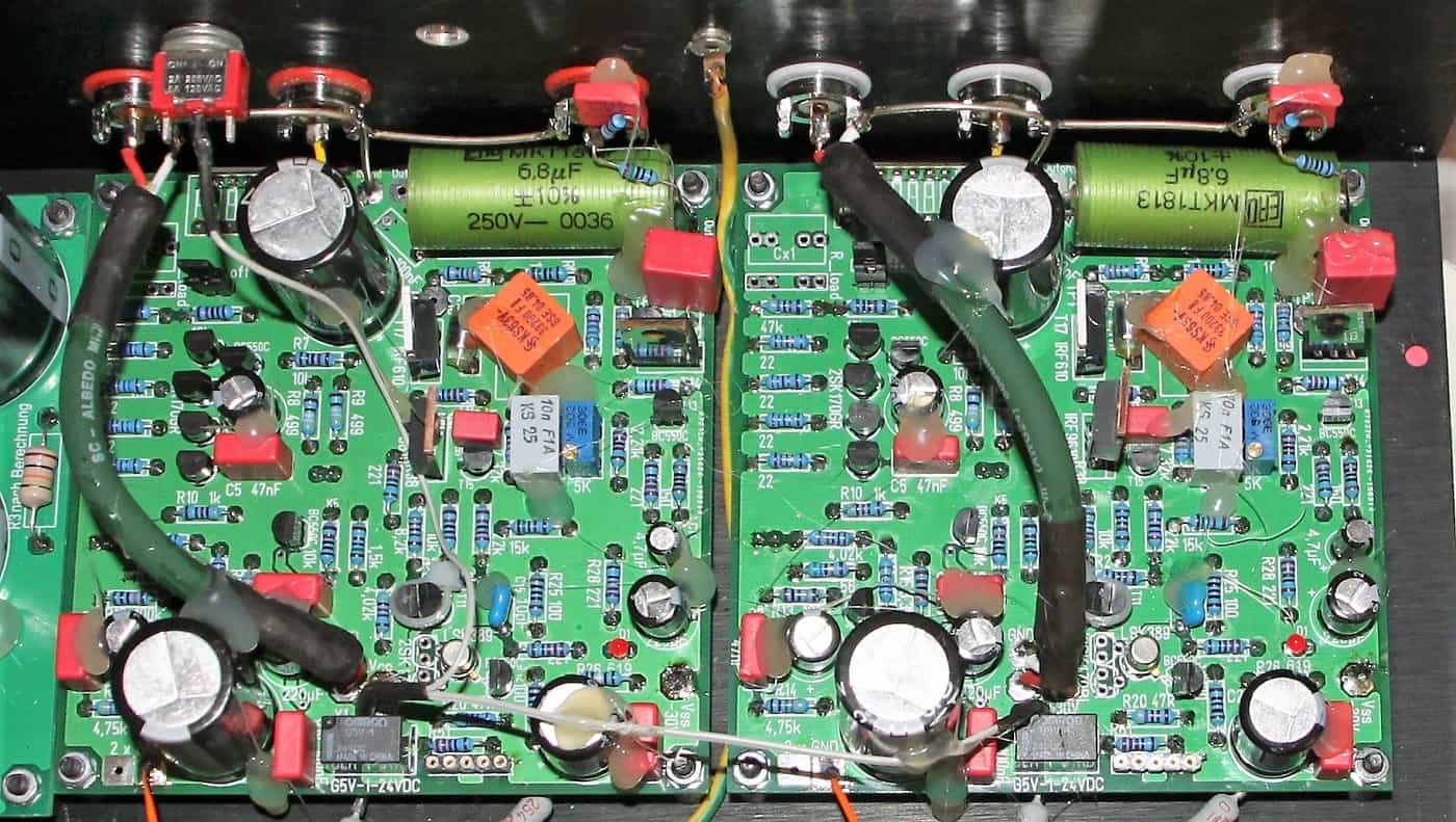
Checking the MC-part
To measure the corresponding voltages, I short the input. A piece of wire underneath the circuit board between the input and GND is required here. The input jumpers should be plugged in, otherwise the input will be in the air.
First, I measure the voltage across the source resistances of the matched 2SK170GR. At 22Ohm we do not want to measure more than 55mV in total. This corresponds exactly to 2.5mA and thus to the 10mA required by Nelson Pass for the 4 matched input Jfet in total. With well matched transistors, the voltages will not differ too much from each other. By the way, BL types can also be used here. Then the recommended maximum voltage is 90 mV, i.e. slightly above 4 mA.
The voltage at the emitter of T6 will settle at about 25V. And thus the voltage at the base of T5 through the voltage divider R6/R7 is logically half. These voltages are already present shortly after switching on.
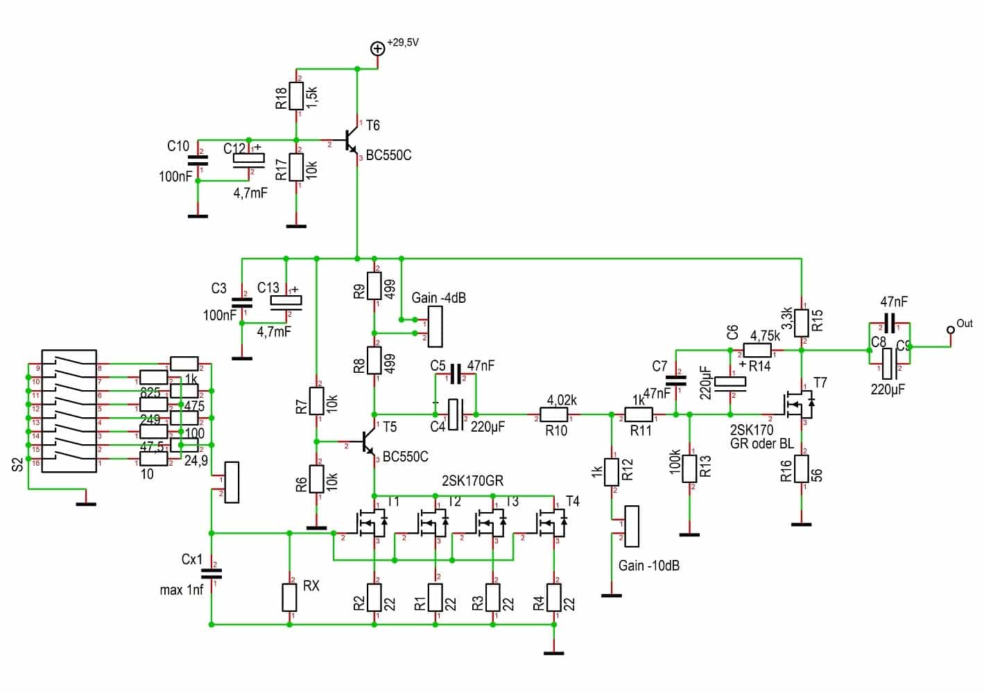
Now we're measuring the voltage across the source resistance of T7. Depending on the type, the voltage should not exceed 200mV (BL version) or 100mV (GR). As already written, it can take up to one hour until the voltage has stabilized.
This is exactly how it behaves with the voltage at the drain connection of T7. Here 11.9V should be measured for the 2SK170BL or 18.8V for the 2SK170GR.
When we have taken these hurdles and the tensions are all halfway right, we connect the device and test the function. By the way, I didn't have a runaway at setup. After a longer waiting time the tensions always adjusted correctly. A small deviation is not a problem either.
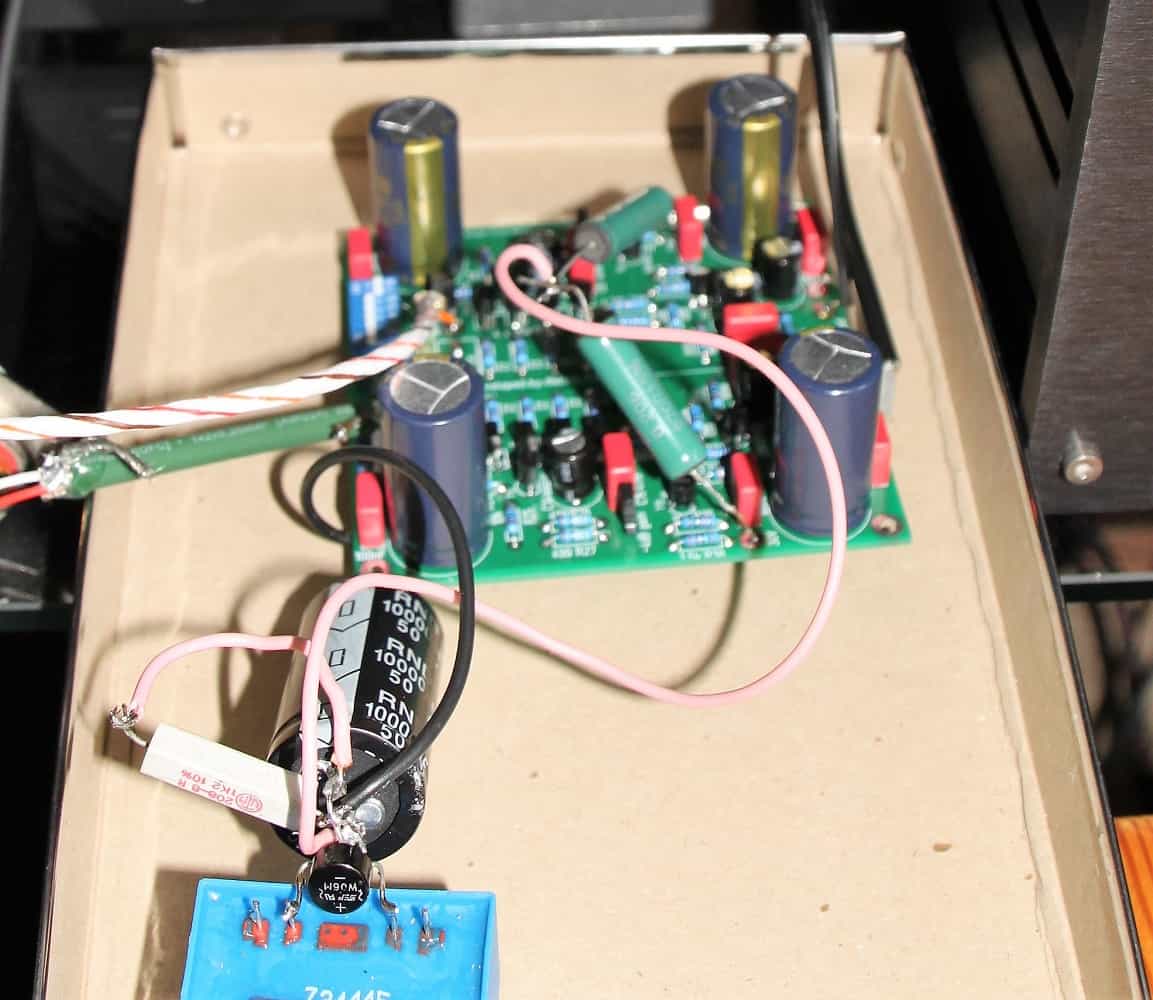
first Test
with provisorish PSU
For the first connection I always use an old Cinch cable that I have halved. This is connected to the output. For the input I made a similar cable.
Now you can play at the DIP switch and look for the best setting for your system. The recommendation for this is: Set approximately 10 times the resistance of the DC resistance of the system and then test in both directions. There are even MC systems that are happy with a termination resistance of 47k.
For deactivating the DIP switch and installing a fixed resistor, see below for further information. If nothing crackles, cracks or tickers, the boards should be installed in a housing.
If there is a noise even though the needle is not lay on, I recommend to mount Cx. The value can be between 100pf and 1nf. This does not harm the sound of most systems. Just try it out and then try it out. Please pay attention to a good quality.
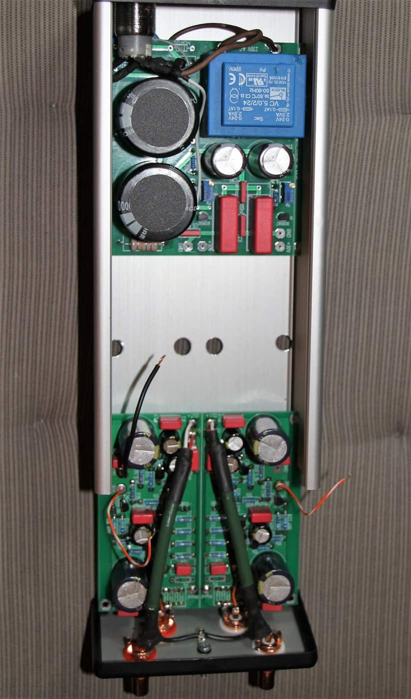
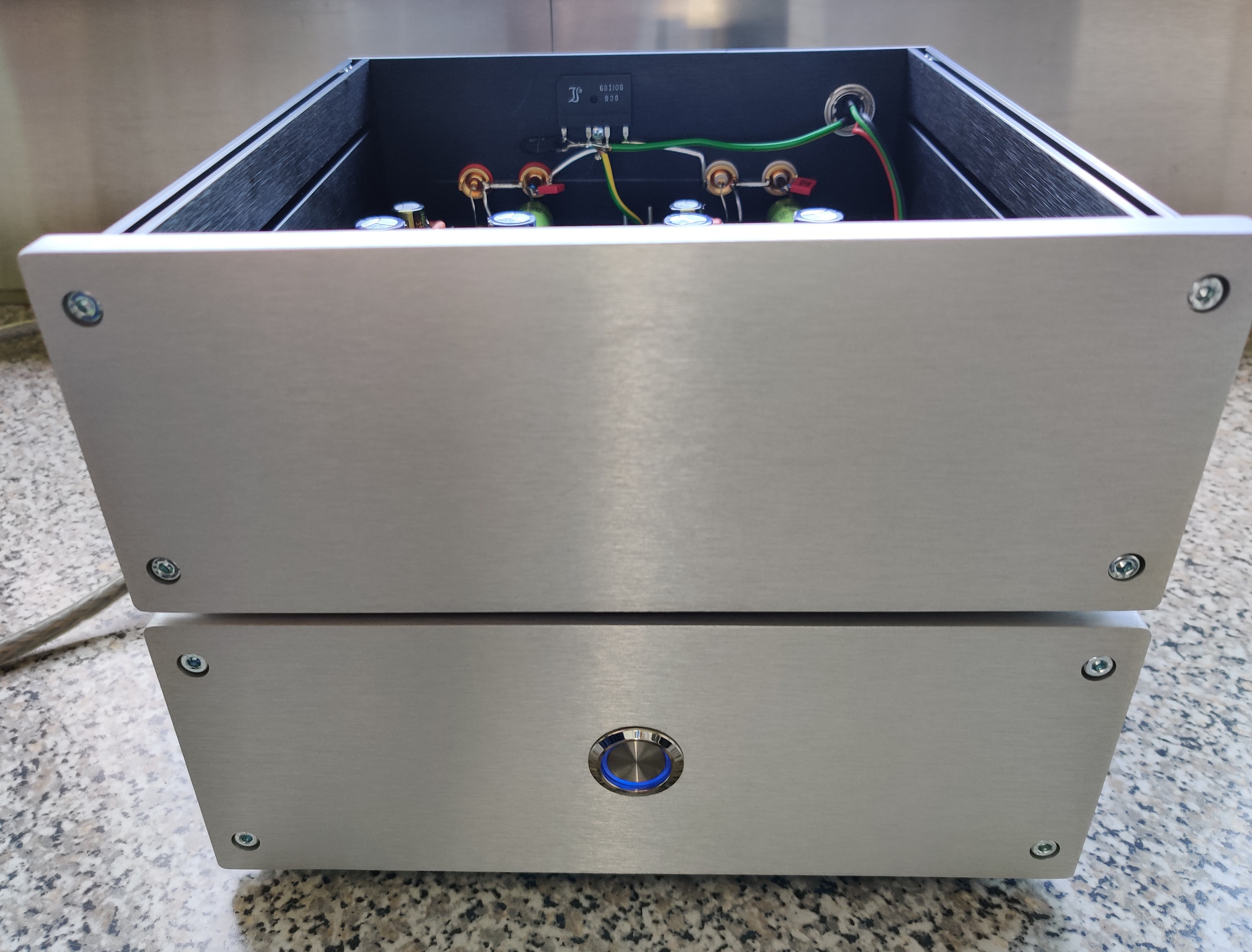
Installation in a housing
The housing used by me has the dimensions 221x100x53mm. The boards fit exactly. Now ONLY two pairs of RCA sockets, a mains switch, a housing connection and a mains cable have to be accommodated or passed through.
Now that I am aware that many users always leave this device (or similar) on the net, I would recommend to omit the power switch.
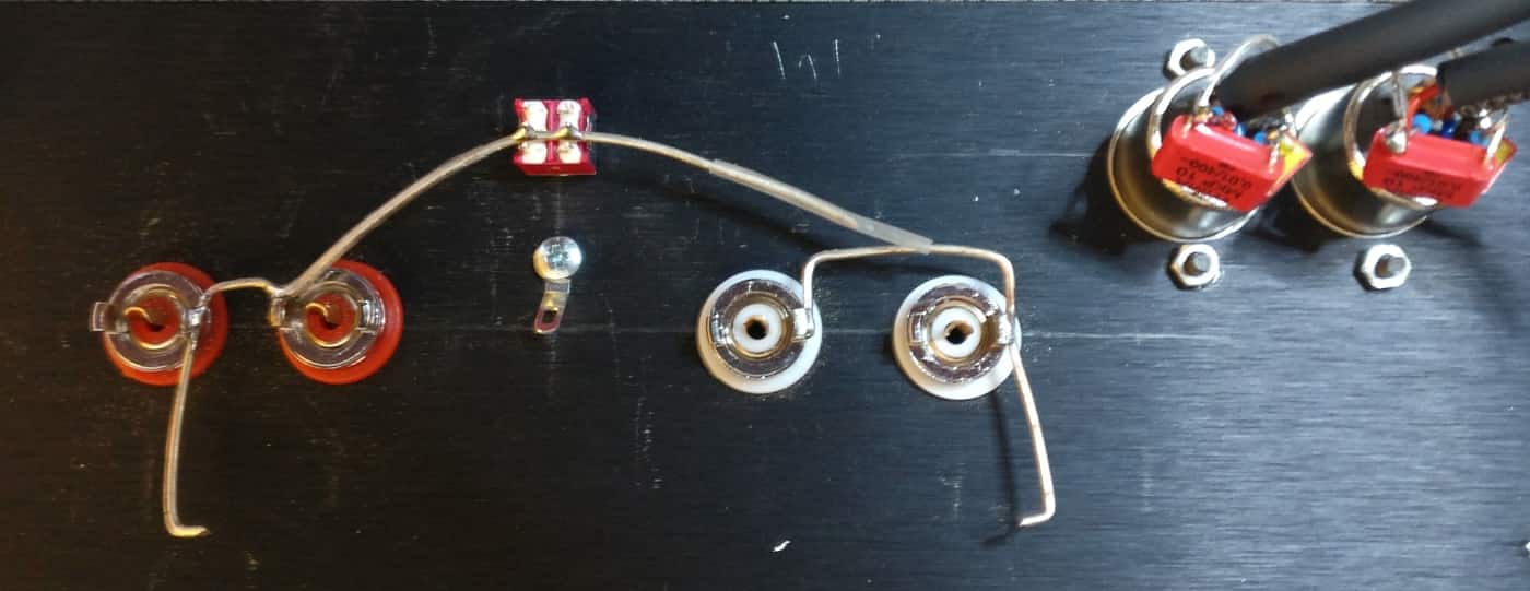
Cinch connectors
I'll start with the cinch sockets. I mount the input sockets so that I can connect the ground directly to the PCB with a short wire. The hot wire can then also be very short.
I used to use the Albedo Sommer Cable MK2 as my cable. Meanwhile I changed to the Summer Cable Stage 22. This is extremely flexible, can be easily processed. The missing aluminium insulation foil is not noticeable on the short piece being processed here.
The output sockets continue. I mount them just above. One should pay attention that these do not sit too far outside, so that they do not hit against the electrolytic capacitors placed there.
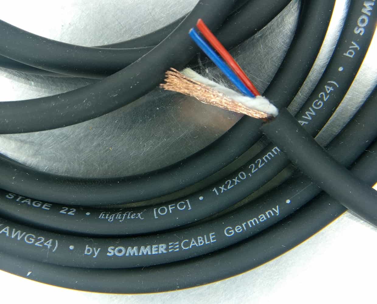
Sommer Cable
Stage 22
Now I'm installing the power switch. This is placed on the opposite side. To the right of the transformer there is space. Of course it is more highend to simply leave out the mains switch. But I don't feel very comfortable with it.
I take the power cord out of the earpiece underneath the power supply board. A hole in the underside, in which a plastic sleeve is inserted, allows flexible movement of the power cable.
I thought the result was well worth seeing. You had to open the walk to be able to make settings, but that was actually very easy. Since I had once again built twice, I set up a device in the bay to be taught a better lesson.
Somehow the buyer did not manage to open the device. In addition, the device sounded extremely bad (it is understandable if it is not adapted to the system) and gave it back. Not without forcibly pulling the circuit boards out of the case first.
You can only wonder about some of your contemporaries. The quintessence was not to sell or to secure the device against vandalism.
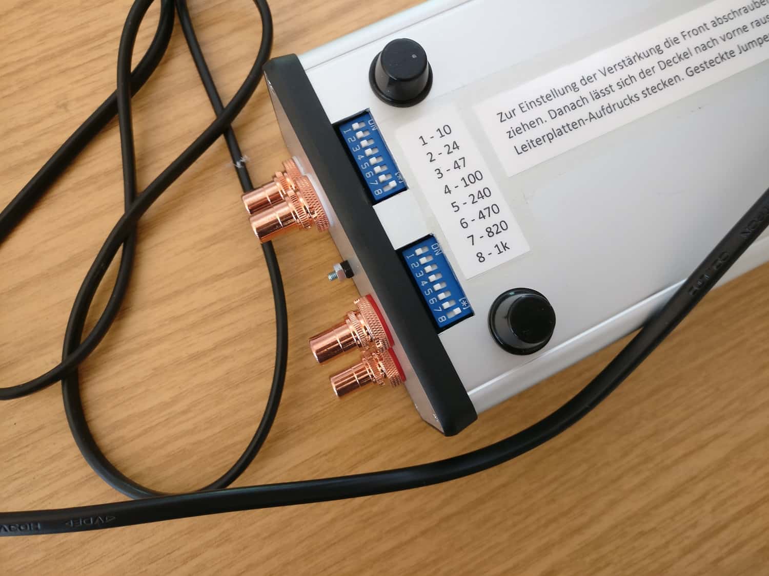
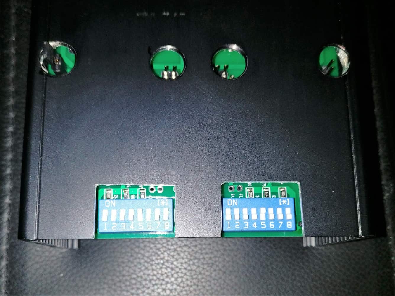
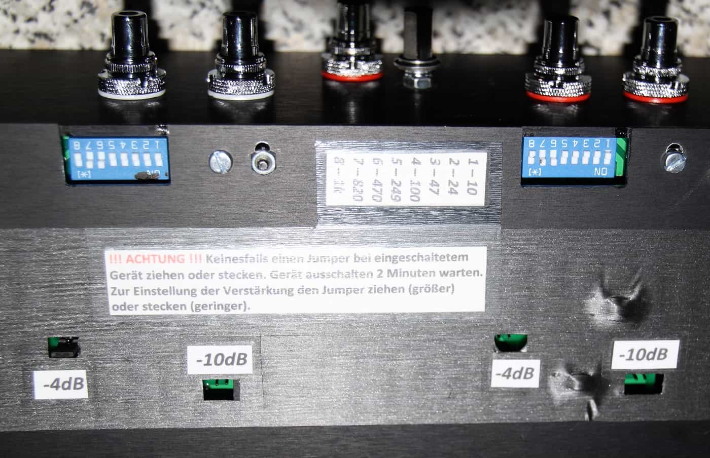
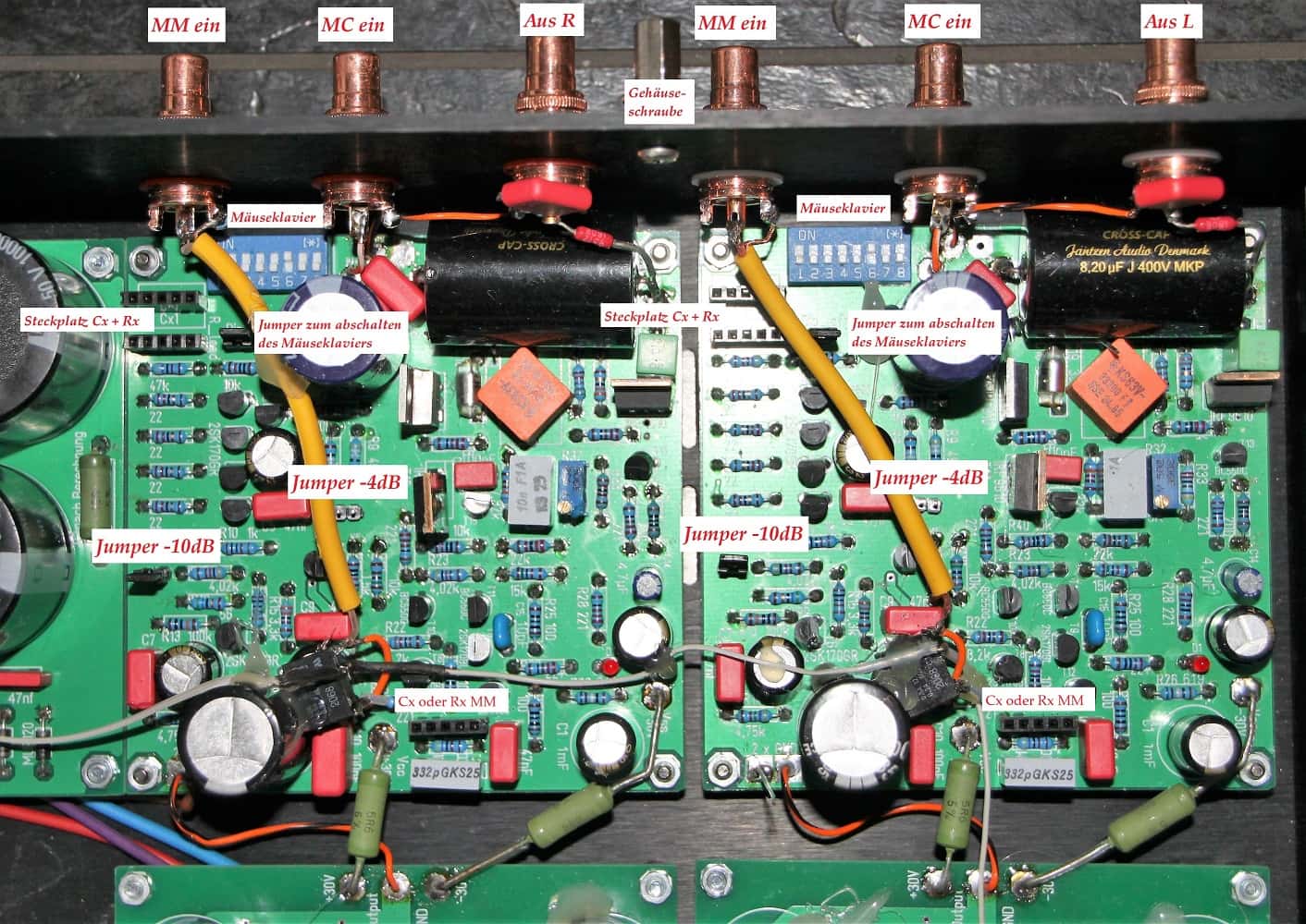
DIP-Switch
I solved the problem as follows: The bottom plate received bursts below the DIP switches. I now simply inserted these from below and got access from outside.
Jumpers now! Four bores in the right place (be careful, measure exactly), the plug connectors inserted from below and they could be operated from the outside as well. The circuit board must now be inserted one level higher, since the plug connectors for the jumpers otherwise collide with the base plate, but the height is still sufficient for the electrolytic capacitors. A good solution, I think.
That was it with the XOno MC preamplifier. Further down you can get rid of constructive criticism and remarks.
Drilling from the inside
completely filled
Outbursts from below
XOno unbalanced (Cinch only)
After I had already liked the sound, I wanted to build a complete XOno preamplifier myself. The RST boards I had given away in the meantime, because they were too big for my needs.
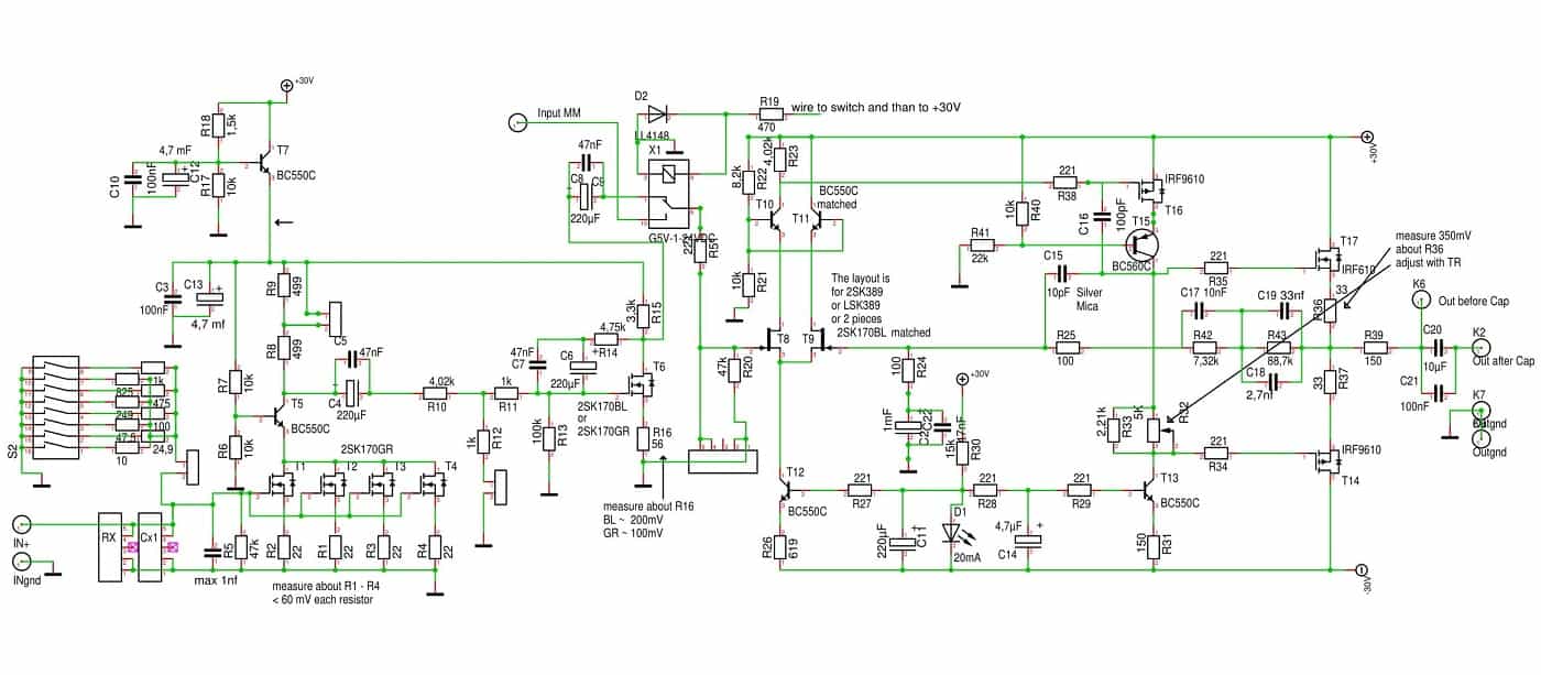
Circuit MC/MM unbalanced
My system is designed asymmetrically. So I was looking for the possibility to only pick up the unbalanced signal and save myself the construction of the balanced part. The circuit diagram immediately shows that the negative half-wave is taken from the finished signal and then added to the unbalanced output via a corresponding circuit.
The disadvantage of the missing part of the circuit is the lower heat dissipation. Mr. Stens immediately pointed this out to me. Therefore I get the slots of my devices masked.
In numerous forums you can read that the preamplifier actually sounds better if it is in operation for a long time (and therefore well heated). The recommendation is even to leave the preamplifier switched on at all times.
So I ignore the hint (for me the sound in cold condition was already a clear step forward) and designed the circuit board for the preamplifier without symmetry. Since we also need a negative operating voltage here, I used adjustable voltage regulators.
These voltage regulators can be connected in such a way that they operate as adjustable constant current sources. I got to know this principle while studying Allen Wright's "Cookbook". He equipped his tube heater with one LM317 each. This works wonderfully and forms an additional buffer against humming.
The circuit is described in the data sheet of the voltage regulators. Therefore I save the circuit diagram here. Wayne Colburn used a discrete voltage regulation with MosFet in the Ono (according to information from the net). Later (XOno) he switched to fixed voltage regulators.
I now use for the power supply:
- toroidal transformer 2x24V/min 200mA
- one board with rectification and CLC-sieving
- two boards to generate +30/-30V each
This means that I have the balanced voltage +30/-30V twice, so for each channel separately available. Since I only use a single rectifier board with a mains transformer, there is a common ground. No problem for me, as my system is asymmetrical.
If you want to rebuild the device and prefer a separate ground connection, you can simply add another rectifier board with mains transformer. This is a wonderful way to separate the grounds.

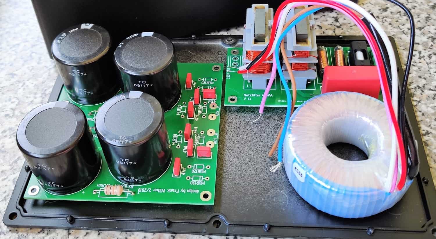
rectifier board
4x10MF with choke

adjustable PSU
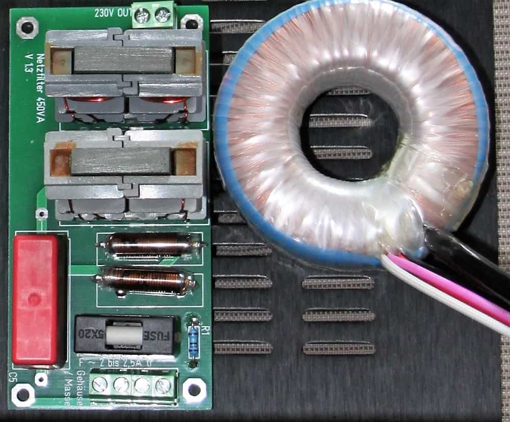
toroidal transformer 2x24V/600mA
mains filter included
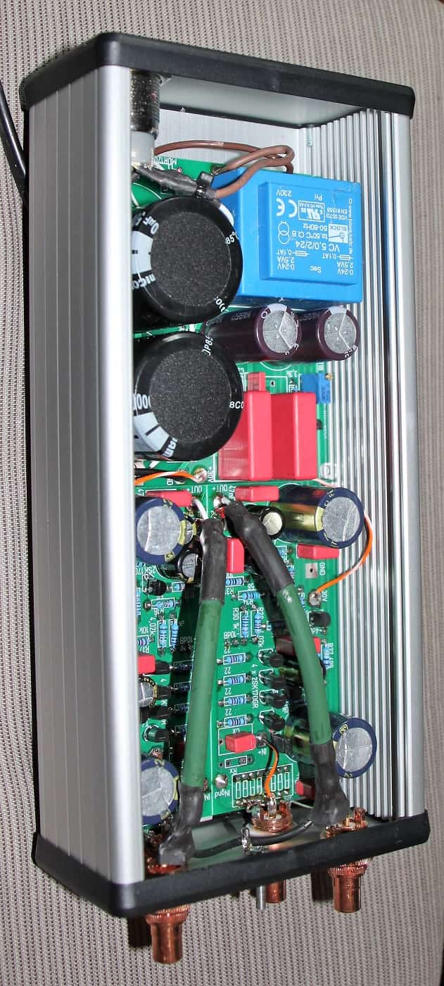
Mounting the preamplifier circuit board:
First of all a note about the components. You can find the exactly used components in the download section. Again the BC550C and BC560C are used as replacements. The BC550C must be matched as accurately as possible. Then there is the topic 2SK389. Alternatively you can match a pair of 2SK170GR or BL (lower IDSS).
There are also some in the bay. But I would advise you to invest a little more because the alleged "new product" is definitely not real. After all, these treasures are no longer produced. Otherwise there is still the company Linear Systems. The LSK389A or B are a direct replacement for the 2SK389GR or BL. If you want, you can get a pair from me.
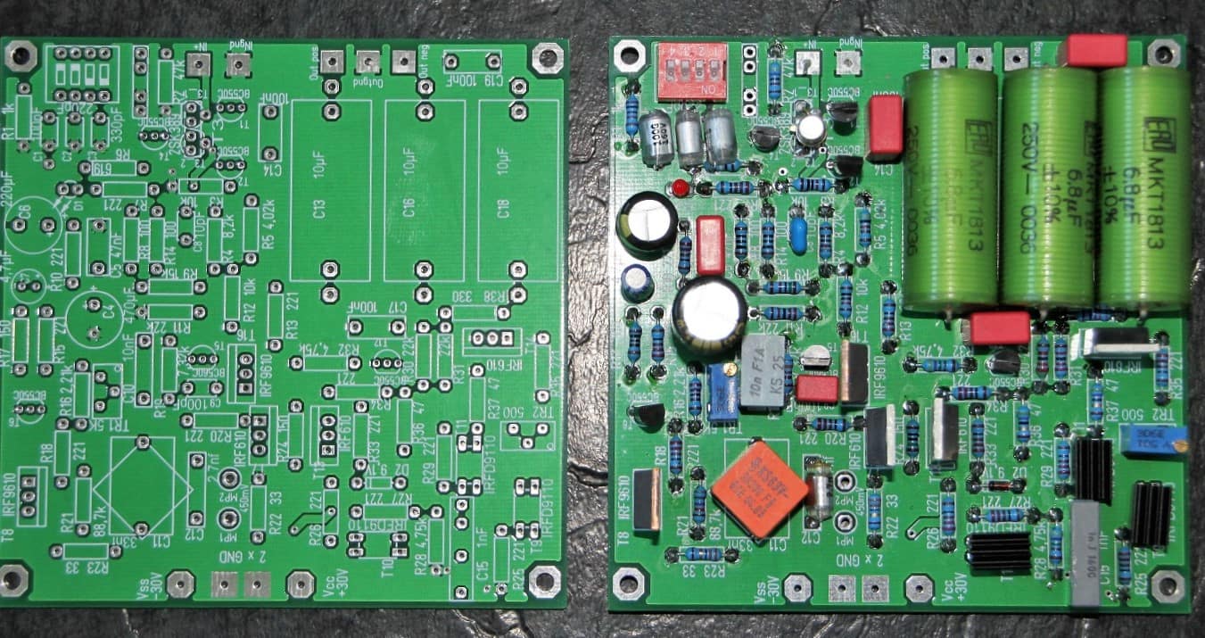
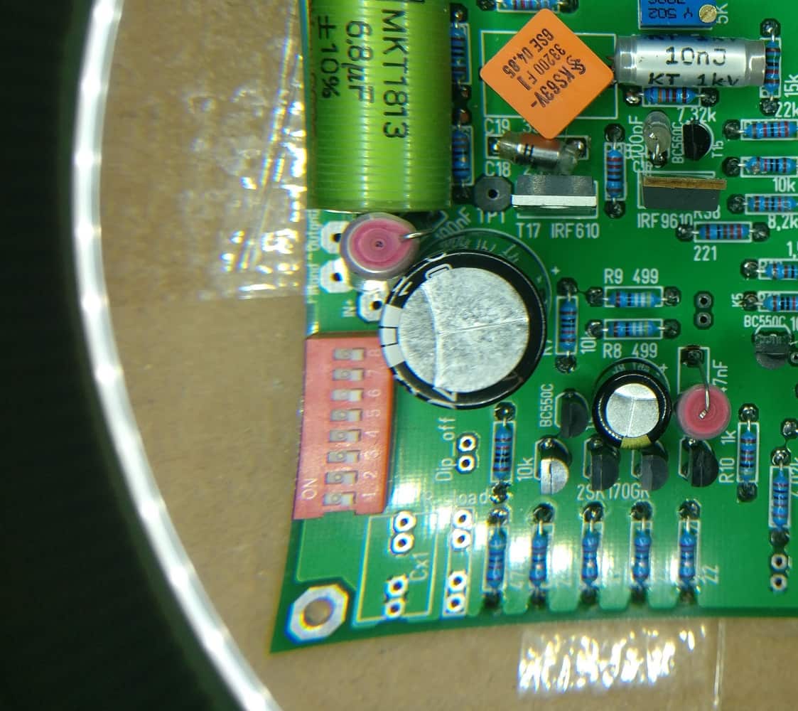
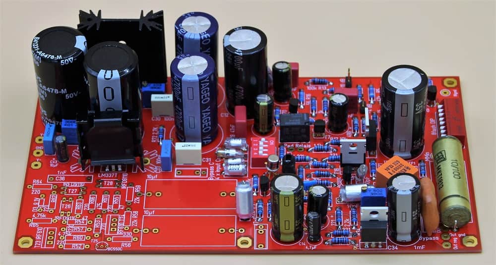
Mainboard
full mounted
For the LED I use a red 20mA variant in 3 or 5mm diameter. This is connected to +30V via a series resistor. In the circuit diagram from 1997 the value is 6,8K. Due to a discussion of the XOno community on DIY audio I use a 15k resistor here.
Please bring the trimmer to the middle position before installation. Otherwise it can happen that one of the source resistors burns down. With the correct setting, only 350mV should drop here. However, the voltage can be much higher with wrong setting. And the 0.6W types can't handle that.
The components are assembled as in any other project, from small to large. I make sure that the source resistor R36 of T17 looks two millimeters further out, so that I can still attach my terminals for measuring the quiescent current.
This is exactly how I proceed with the resistors R26 (emitter T12) and R31 (emitter T13). These are responsible for the two constant current sources. The values printed on the board are valid for my batch of transistors and Led. They are for reference only. Here you have to measure and calculate.
After everything is settled, I recheck the polarities of the capacitors and the correct installation of the transistors and Mosfets. I know that's easy. Still, it's often happened to me to have a Mosfet mounted wrong round. And then there's usually all around it damaged By the way, the exchange costs much more time than an exact control!
All ready? Short the input and connect the measuring leads via R36. Then we switch on our artwork. The now slowly lit red LED should calm our nervous system. Now we measure the quiescent current via R36. With the trimmer we turn down the quiescent current first of all. It can happen that the voltage does not react until you have made two to three revolutions.
After a running time of a few minutes we again check the quiescent current. It should still be below the required 350mV. Now we adjust the supply voltage correctly. Optimal are +29,5/-29,5V. Now it becomes somewhat more complicated; the constant current sources are calling.
The constant current sources (ccs):
Please make sure that the amplifier has warmed up, the quiescent current is set correctly and does not change before performing any subsequent measurements/checks.
2.1 mA should flow over the emitter resistance of T12 (R26). Wayne Colburn uses 475 Ohm here and expects 1.0V voltage drop. In my component constellation (matched 2SK170BL and also LSK389A with BC550C) the voltage drop was always approx. 1.3V. So we calculate R=U/I, so 1.3/0.0021 = 619 Ohm. Meanwhile I have built about 8 or 9 devices. At 619 Ohm I come pretty much to 1.304V. Pretty perfect.
We continue with the next constant current source. Here we would like to have a current flow of 6.7mA at 150 Ohm (1V). With me it becomes always scarcely 1.340 V. So just put in 200 Ohm; Fits pretty well again.
So far so good. As already described under the MC part, I connect the temporary stripping and test. I assume that it will work just as well as I did and that we can get it into the case.
The housing:
I think the pictures shown here are meaningful enough. If something is unclear, please just write. I will then be happy to change the project description.
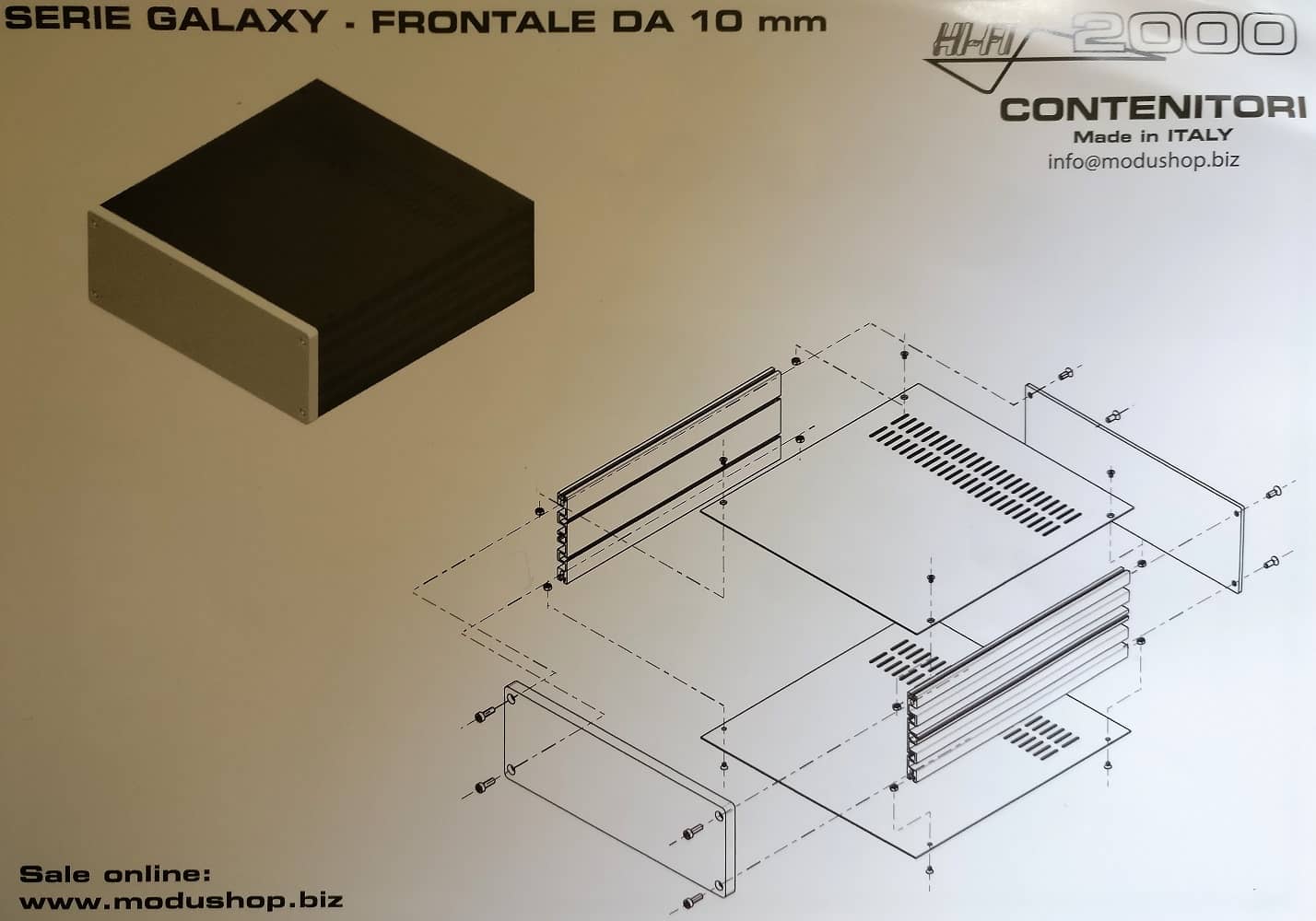
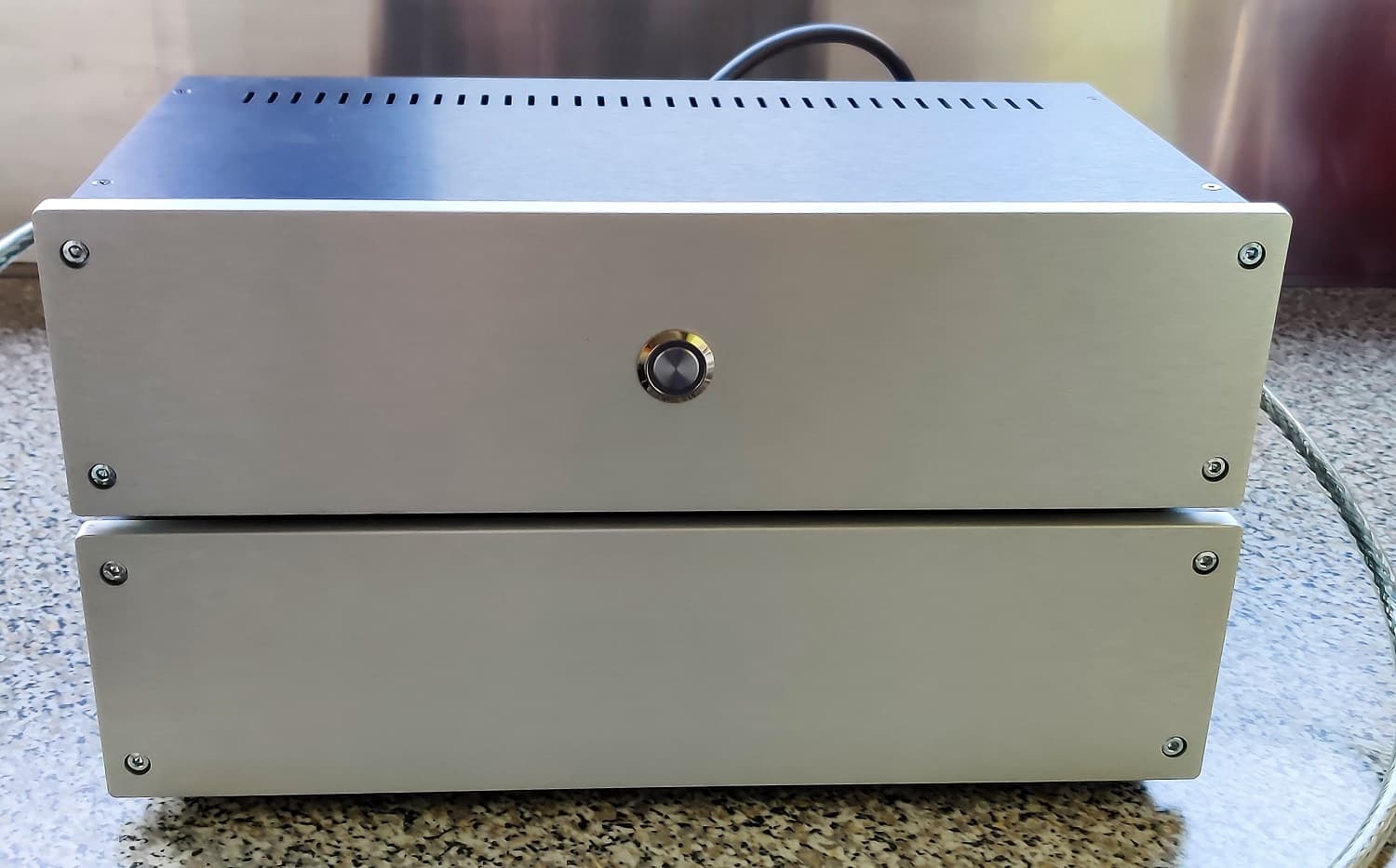
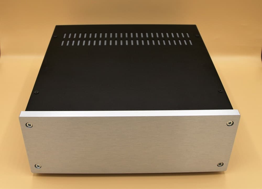
Galaxy Maggiorato GX383
2 height units
I like to use the housings from the Modusshop in Italy. They are available in many sizes and variations. If you order them there, you will have them at home after three days at the latest.
For the unbalanced version we have to accommodate 5 boards in the dimensions 100x100mm and a small toroidal transformer. An interior space of 330x220mm should be available at least. The variant Galaxy Maggiorato GX383 offers exactly this space. The case is 80mm high (inside). I always order the version with the 10mm front panel. Bottom and lid are then made of 3mm aluminium. This is easy to work.
Update to the housing
As you can see in the picture "partially mounted" below, the base plate looks quite scratched. This is just abrasion from the fingers or fingerprints. It's really easy to wipe it off. However, I have to say that the black aluminium surfaces react immediately to skin contact. Then they always look a bit dirty.
In the meantime, I always order the powder-coated sheet steel version. It always looks nice and clean. As front panel I prefer the silver one, because it is much less sensitive to dirt. But everybody should keep it as he wants it to be.
Breakouts
This is where the jumpers and DIP switches come into play. If you decided before not to open the case, you soldered the jumpers (pin strips) and the DIP-switches to the bottom. This means that two cut-outs for the DIP switches and 4 holes for the jumpers must now be made.
Let's leave the jumper for switching off the DIP switch in the case. This is probably only used very rarely.
The breakouts for the switches can be produced very well with a jigsaw. The cooling slots in the drill holes can easily be enlarged. Once the holes and cut-outs have been made to fit, it is finally time to install them.
And one more thing: I always tape the openings of the enclosure so that not too much air can circulate. As is probably known, this device should be well heated.
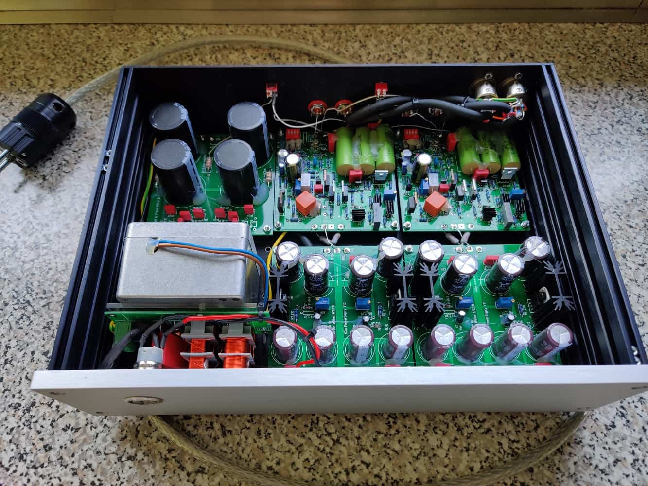
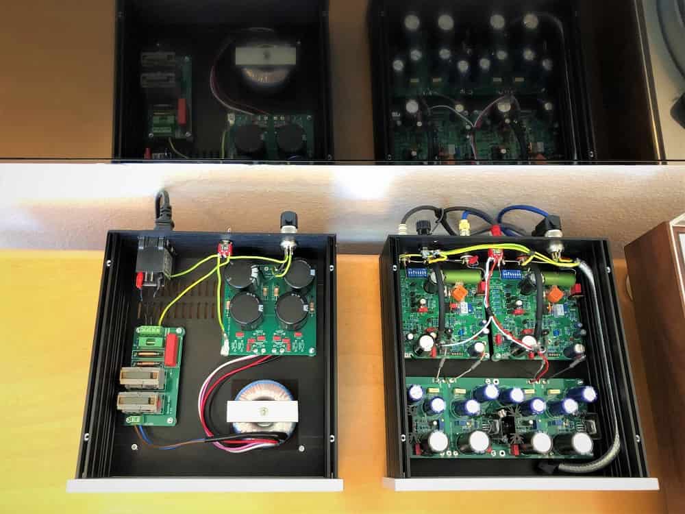
I build as follows: Mains transformer on the left directly behind the front panel, behind it on the left the rectifier board. The mains filter shown in the pictures is no longer used by me. The boards for voltage regulation are located in the middle and right behind the front panel.
The motherboards are located behind them. These should not be mounted too close to the rear panel, as the output capacitor may not fit completely on the board. By the way, this is a very nice way to establish the connection to the cinch sockets.
I push the boards on the bottom plate and draw the holes. Please make sure that the back wall and the side parts are placed on the base plate. This space (10mm at the side and 3mm at the back) should remain free. After the drilling I start with the screwing. First the toroidal transformer. I pad this with sponge rubber or felt. Then it does not transmit vibrations to the case.
The rectifier board continues. I now solder the connection cables. This will be the final setup. The boards for the voltage regulation are mounted so that the input voltage is directly behind the front panel. So we have the solder pads directly behind the motherboards. So a short connection.
Wayne Colburn has made this connection with a 5.1 Ohm/2W resistor. Since high-quality wirewound resistors are not cheap, I always take what is just in the offer. The actual value is not so important. It should not be too high (kleiner 10 Ohm), so that too much voltage (and power) does not drop. So I don't need an extra cable. Just a little shrink tubing for the connection wires. This connection can be made after all circuit boards are installed. I soldered in the resistors from below. I liked that better somehow. When the wiring is finished, I insert the side panels.
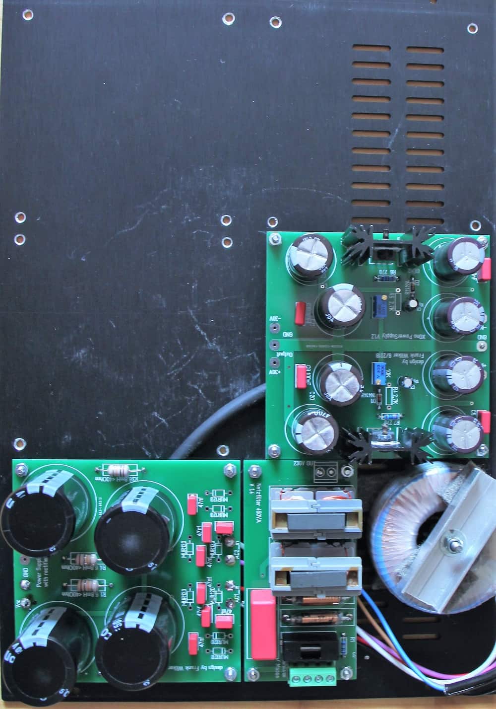
partially assembled
toroidal transformer 2x24V/600mA
mains filter included
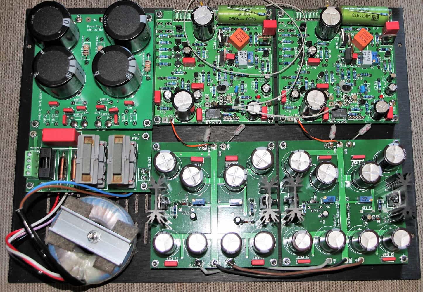
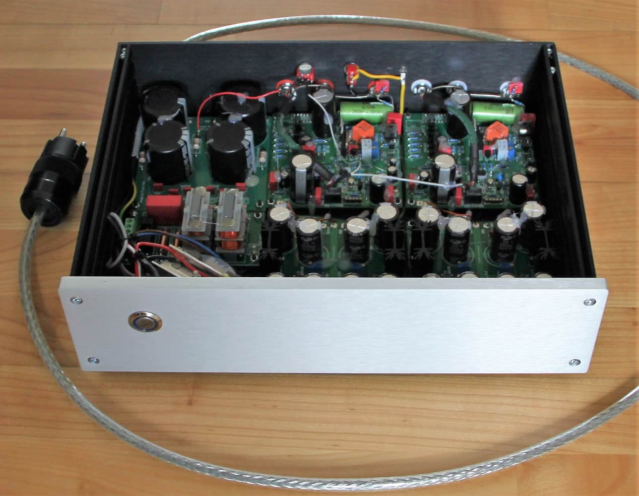
Complete view
fully wired
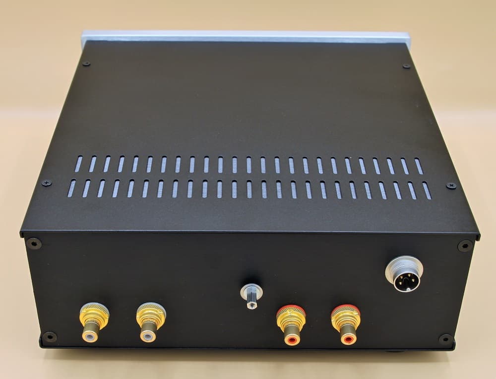
Now we come to the back wall. Here we need holes for the input and output sockets, the mains cable and a housing connection. In addition, we have decided beforehand whether we want to use the MM input and place it outside. If yes, we also need two input sockets for the MM input and a hole for the MC/MM switch.
By now it should be clear to everyone where the real work lies in such a project. Please don't try to get it done as soon as possible. Especially the building of the house is very demanding. So keep your head up and hold on.
Drills
Cinch sockets inserted
I always insert the power cable into the back left of the case. Please use a screw connection with strain relief. If you don't use a mains filter, you should also use a fuse holder for screwing. I mount the Cinch sockets MC_ein just above the board in the area of the input solder pad, logical. This gives very short signal paths and you can do without a shielded cable.
If MM is also desired: I set the socket to the same height about 25 to 30mm to the left of it. The output socket is mounted slightly higher, so that the middle connection is above the output capacitor (connection side at the output). I place the hole for the MC/MM switch so that the switch is between the two capacitors of the rectifier board. So that it will not become so difficult later, I solder already times correspondingly long cables on.
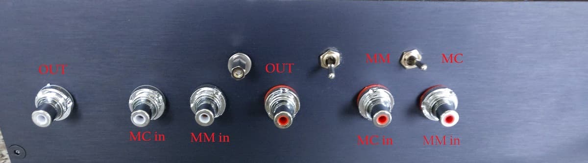
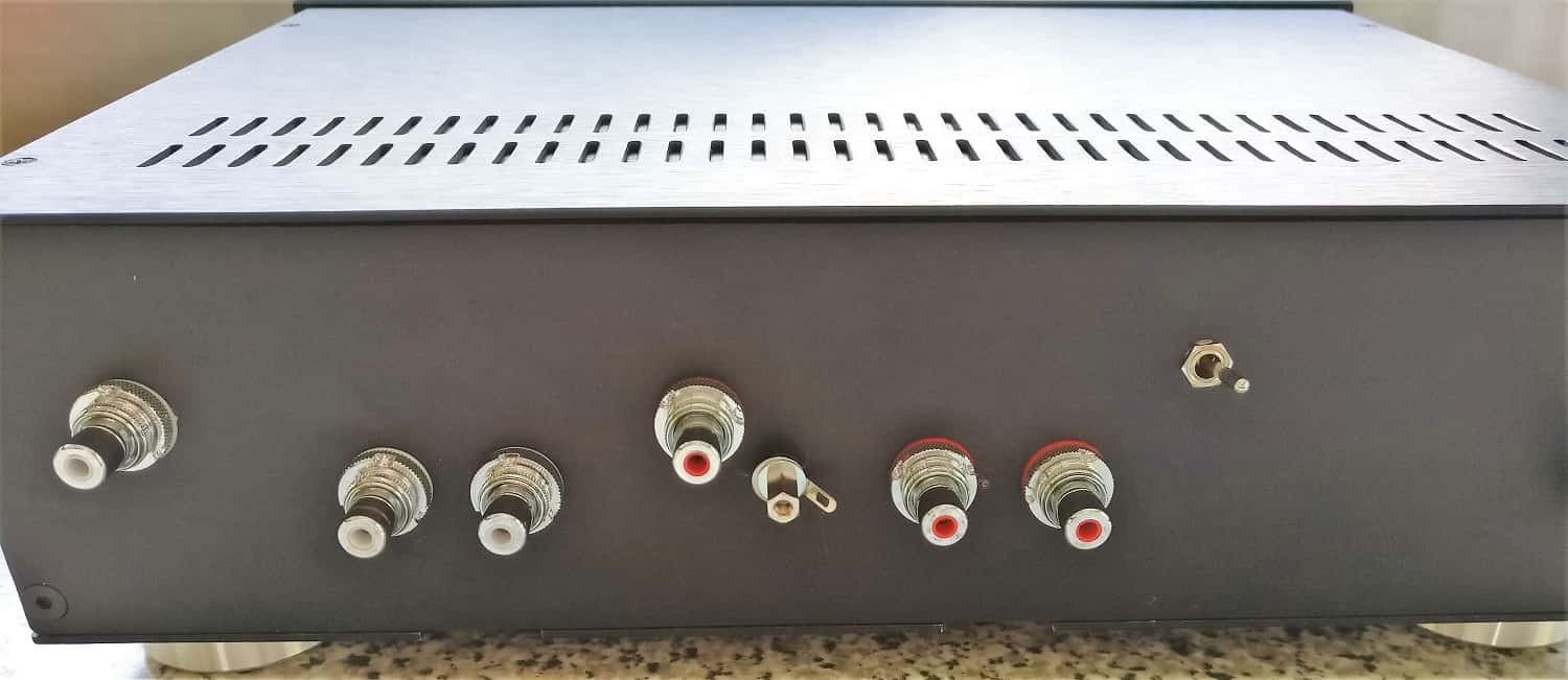
rear side
Including lettering
Now another housing bore, either 3 or 4mm. This hole should be made so that the ground cable of the turntable cable can be easily connected when the RCA sockets are disconnected. These were all holes.
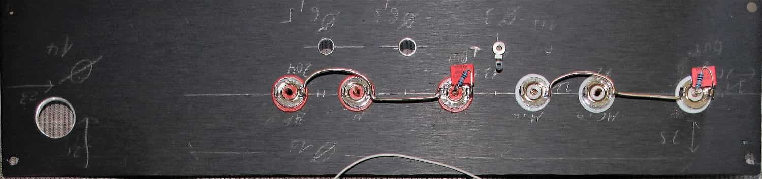
Now the cinch sockets, switches and cable bushings are installed in the rear panel. Before I install them now, I measure the cables with which I connect the respective sockets. I use teflon insulated silver cables. The insulation does not burn during soldering and the cables are of extremely high quality. I solder the two cables for GND_out and GND_MC_in, as well as MC_in already on the circuit board.
Additionally, I apply a 150 Ohm resistor to the base of the output capacitor (or solder pad output). This resistor is used to make the connection to the output socket. ATTENTION: The picture shows a wrong connection. A 100k terminator resistor is connected to the 150 Ohm/output capacitor connection. The other side is connected to GND. At the same time we solder in a 10nf foil capacitor (or mica/polystyrene).
Boards wired
Boards wired
older version
Once all this is done, we can install the back plate.
- Now pull out and connect the mains cable. Connect the cable either to the mains filter or to the fuse holder.
- MC RCA socket solder on.
- Output RCA solder
- MM-Cinch solder cable
If you have chosen the mains filter solution, I will pull a cable from the ground connection of the filter to the housing screw. If you want a lift-ground switch, connect the ground cable to the switch (which I mentioned earlier) and the other side to GND. This solution is simply wrong, but still helps to fix hum sometimes.
I don't have this switch anymore.
Housing opened
Lapp ölflex power cord
Rear side
without Ground-Lift
Finished project
Now put the lid on, switch on and ENJOY MUSIC!
XOno now symmetrical - MM only
One of my acquaintances asked for a pure MM solution because he doesn't have an MC system and wanted to save himself the MC section. Of course, this version is also a bit cheaper, because the expensive input transistors are no longer needed.
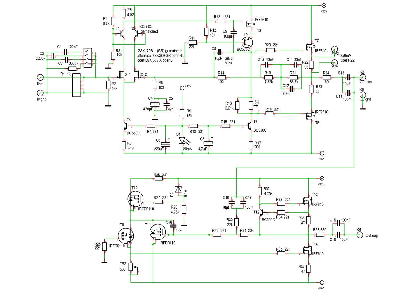
Circuit diagram
symmetrical
A subarea already existed, so the development should not be a big effort. Said and done; I finished the complete circuit with symmetry part. You can simply choose whether you want to equip the symmetry part with.
A small note about the amplifier part of the negative half-wave. In the past, a potentiometer was used to set the DC part of the output to 0V. The circuit was designed to operate without output capacitors.
As this did not work as desired, the output capacitors were inserted. This keeps the remaining DC voltage away from the following stage/device. The trimmer was then replaced by a fixed resistor. On my circuit board I left space for a trimmer. But a fixed resistor does as well.
Board assembled
Roederstein NOS
The boards are assembled as described above and installed into the housing. The power supply unit is identical to the version described above and is described in more detail below. I always connect a 2.2uF Roederstein and a 1uF Wima capacitor in parallel to the 6.8uf Roederstein. The three IRFD 9110 get glued heatsinks.
The back plate is provided with the appropriate holes:
- Power cord
- MM input RCA socket
- Output RCA socket
- XLR sockets (only for the balanced version)
- Switch output XLR-Cinch (closes the negative half-wave short via relay)
The termination at the XLR sockets is carried out as follows:
rear side
with XLR connectors
Pin 1 of the XLR socket is connected to GND. Pin 2 is connected via a 150 Ohm resistor to the output capacitor of the positive half-wave (see above). Solder a 100k terminating resistor to the 150 Ohm/output capacitor connection. The other side belongs to GND. In parallel we solder a 10nf foil capacitor (or mica/polystyrene).
From the output capacitor of the negative half-wave (neg out) we go directly to the XLR connector 3. At the same time we solder a 100k resistor to pin 3 of the socket. The other side is connected to GND. In addition, a 680pf foil capacitor (or polystyrene/Mica) is connected in parallel.
After installation in the housing, nothing should stand in the way of listening pleasure. Always remember: The capacitors need a lot of break-in time.
Power supply unit XOno all variants (except MC)
The power supply construction is the same for all variants (except MC). We need +/-30V per channel, which are generated on one board each. These two voltages are generated on these boards by adjustable voltage regulators.
Through the switching principle, the voltage regulators are connected as constant current sources, they form a buffer to the input voltage and block a part of the ripple voltage. As input we need here at least 2.5V voltage surplus.
rectifier board
equipped with SMD-UF diodes
power supply board
adjustable +/- 30 Volt
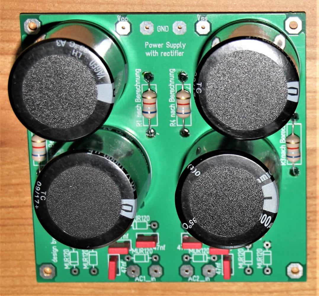
Rectifier board
top
Usually the positive part of the circuit draws max 130mA with full configuration, symmetrical incl. MC part. To achieve this, we need 50% more than AC voltage, i.e. at least 195 mA. As a safety reserve we add another 50% and are on the safe side with 2x24V/300mA per channel. By the way, the negative current consumption is lower.
This brings us to the rectifier board and the transformer used. At 24V AC we get rectified to approx. 34V DC. Usually this voltage is even higher due to a higher open circuit voltage and the fact that we oversize the transformer. With my toroidal core with 24V/630mA for both channels I get a rectified open circuit voltage of almost 40V.
Finally, we have to decide whether the power supply should be symmetrical. The difference is the ground. If I need a separate ground per channel, because I have a fully symmetrical system, I also need two transformers with a rectifier board.
We now build with one or two rectifier boards. Here it goes with ultrafast diodes SMD or wired to the first screen capacitor. The diodes are bridged with foil capacitors to reduce the spikes when switching. Also here we can use SMD or leaded types.
I use one small (or two parallel connected) screen chokes as connection to the following screen chain, as it is also usual in tube technology. The screening effect is enormous. Why not use this advantage here as well? This elegantly reduces any excess voltage so that the voltage regulators are not overloaded too much.
When calculating the screen choke, please ensure that we need at least 2.5V excess behind the second screen capacitor so that the voltage regulators can operate properly. If you like, you can install this part (rectifier boards and transformers) in a separate housing.
Power supply board
adjustable assembled
We feed the now generated DC voltage to the adjustable power supply boards. To test the boards and adjust the final voltage we need either the 2.7k resistor shown in the circuit diagram or a load resistor at the output. I usually use the latter variant, since the board is finally operated under load.
To do this, I connect the +30V and -30V connectors via a 1k Ohm resistor (at least 5W) to GND. After switching on I can roughly adjust the voltage. As mentioned above, we need 29.5V on the amplifier board. The connection between power supply board and main board is done by a resistor (approx. 5 Ohm).
That should be everything. Turn it on, and roughly set it to 29.5V. Then I adjust the quiescent current. Now I check the voltage again and set it exactly to 29.5V. Usually the voltage has changed only insignificantly.
Circuit diagrams and BOM can be found under Downloads.
Miscellaneous
Another attempt
Toroidal transformer encapsulated
When I talk about hum in the next few lines, you will probably say immediately: "Wait, I don't think this thing is humming!". All relative. When I turn up my amplifier 70% it just hums a little.
Since my Devialet has quite something on it, this is not surprising after all. With this position of the volume control I would never be able to listen to music. But look for Hum!!!
Before screwing down the transformer, I look for the optimal position to minimize the very last bit of hum (although this is very small due to the construction).
To do this, I connect the preamplifier and turn up the amplifier so that I can clearly hear the hum. It doesn't take very long to find the right position. For me it's the one shown on the pictures.
This is not only about the position, but also about the exit of the cables.
A little bit more. At some point I noticed that the hum was a little louder when the lid was closed. Actually it is so. The resulting eddy currents cause a stronger hum.
My first idea was a glass lid. A friend of mine had drilled a lid for a preamplifier. Was not bad at all. Or an acrylic plate. You can drill it yourself.
However, the hum can't be heard even at an ambitious volume (and I really do hear very loud). So don't get irritated.
So this hum is more of a theoretical nature. You can't hear it. For this reason the toroidal transformer is also inside the case and not outside.
Whoever has a bad feeling at this thought, installs the transformer and the rectifier board in their own housing and establishes the connection via a six- or three-wire cable.
In the meantime, I have started to outsource the power supply. A batch of power transformers radiated so strongly that the hum was actually audible, even if only very easily. After spending a lot of time on millimeter work and not really getting any further, I decided to always use an external case from now on.
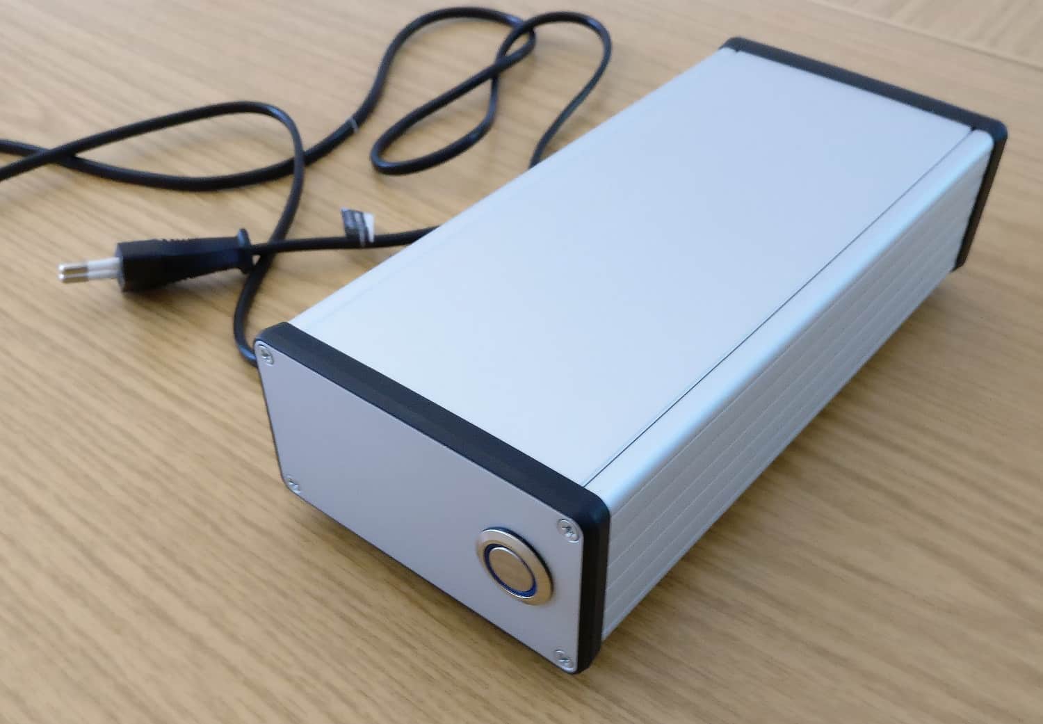
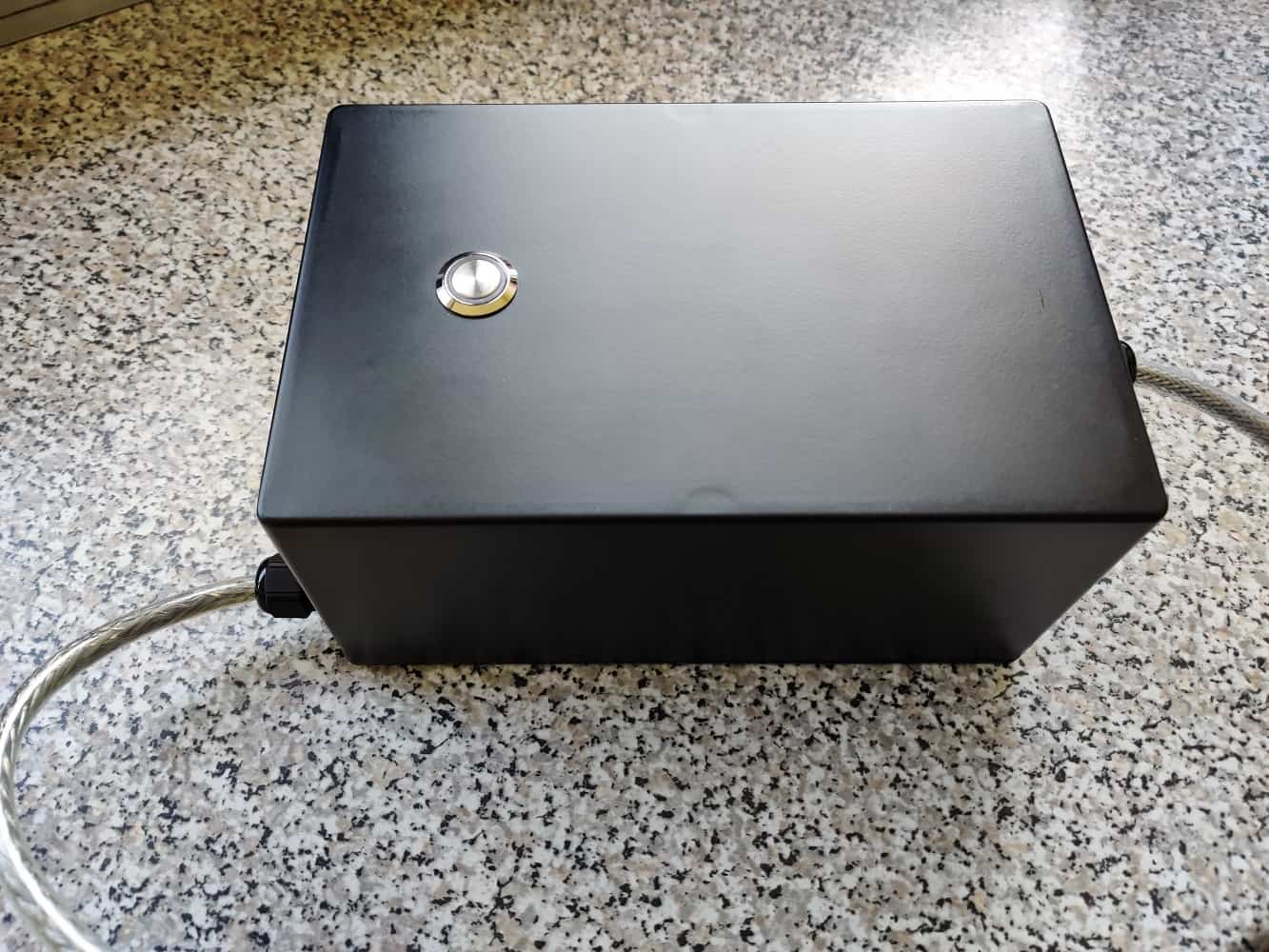
External power supply
Example external PSU
housing Modusshop 2000
Now comes the next task; A housing must be selected. Of course you can follow the Pass Labs setup and use the same case as for the preamplifier. use it. However, you have to be prepared to dig a little deeper into your pocket. Optically, of course, you can show off. As an alternative, you can also use inexpensive aluminum cases from Hammond or RND.
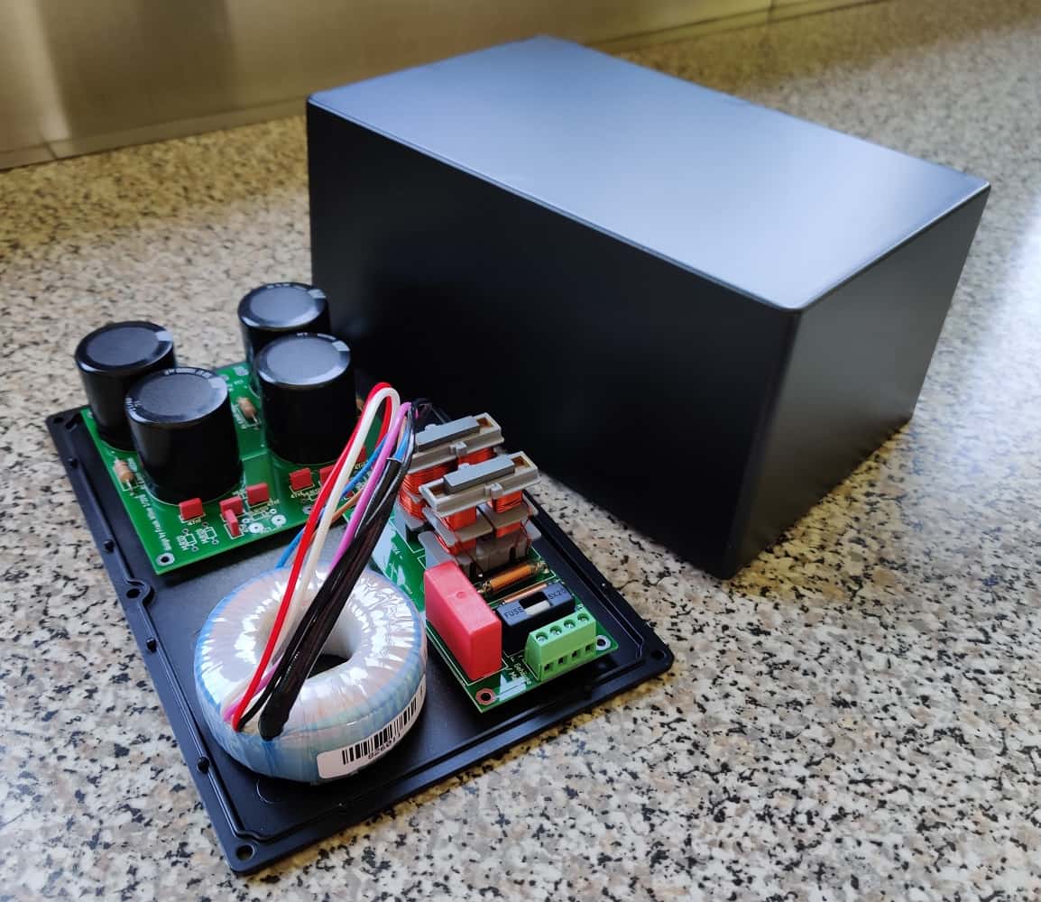
One or two rectifier boards, the mains transformer and/or a mains filter must be accommodated in the housing. So there should be about 120mm width and at least 220mm length available. For the installation of two rectifier boards it is recommended to simply take a slightly higher housing and place the boards on top of each other.
all parts placed
Here I placed the boards and the toroidal transformer provisionally on the base plate.
The power switch goes into the lid of my car. Please make sure that it is not in contact with other parts. This is unpleasant if you have already drilled the hole.
Then we still need holes for the cable entry. Here you have to take care that the hole is not so close to the side wall that the The fixing nut of the cable entry no longer fits. I already know why I point this out.
Cable outlet both sides
With the first external power supply I let the power cable go out on the transformer side and the cable for the output voltage on the board side. Unfortunately this is very impractical for storing it in a cabinet or shelf. The mains cable is now always at the bottom (right or left). and the other cable is led out at the top in the middle.
What else is there to say? I underlay the toroidal transformer with felt. A piece of U-shaped aluminium takes up the screw (also underlaid with felt) and holds the transformer securely in place. The circuit boards are screwed or soldered with the appropriate cables before screwing in. Then install the mains switch and connect.
The power supply/phono amplifier connection naturally requires a high-quality plug. I like to use the 4- or 8-pin version from Lumberg. The plugs and sockets are still affordable with high quality. Please make sure that the plug is the socket version. After all, we pass on a voltage swing of almost 80 volts here.
ext. Power supply unit
compiled
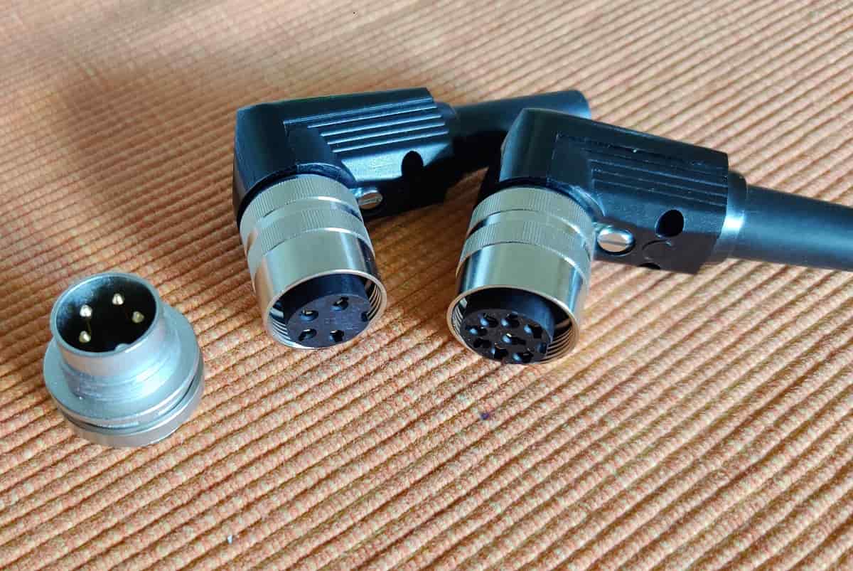
the connectors
socket and plug
external PSU
final view
Screw everything together, feet underneath and done!
sound description
I will first write down a little what the big ones of the guild said to this darling. I quote:
There are few HiFi components that have accompanied stereoplay as faithfully as the Pass XOno. Since the test in issue 10/01 a few manufacturers did catch up to the reference at that time. But the powerful, pithy sound of the XOno has remained a benchmark for the editors to this day. So the interest was great when Wayne Colburn - the preamp developer at Pass - launched a new top phono stage.
This statement of Stereoplay was made in 2011. The opponent at that time was the XP25 (11800 €). This PreAmp then also became the new reference. What I found very interesting was the fact that it was not the sound abilities that decided the test victory. Of course I don't want to question the sonic capabilities of the XP25. But this is interesting if you read a little between the lines.
The Stereo wrote in 2000: "The Pass sounds unrivalled fast and dynamic, even its definition in bass is unbeatable. (price 8900 DM at that time, quality/sound 100%).
My own abilities to give back such impressions are unfortunately very limited. But I'll give it a try.
My first contact were the assembled boards of RST-Audio. I had connected them with long cheap cables. Positively I had used batteries, so of course there was no hum. I personally found the extremely good channel separation and the completely missing hum impressive. But I was missing something of the bumms. For my understanding at that time the sound was a bit thin.
My tube preamplifier was a different caliber. However, the sound of the XOno was very fine and good resolution. Later I switched between tube and XOno again and again, whereby the listening phases with the XOno became longer and longer. Meanwhile I used a device with my own circuit boards. Here the signal path was optimized and all components had been recorded in the meantime.
In the last months I only listened with the XOno, because the boom of the tube amp crystallized later than a little, say Mischmasch. But I don't want to discredit this PreAmp: It already plays on a high level. But the XOno was another house number after the break-in time. Crystal clear sound, hum free and fast.
I think, who found this page, knows what a top device it is and that this preamplifier still has its right to exist today.
Updates
deep insight
When passing on some devices or circuit boards I often noticed that the desire for several inputs became loud. I then offered this as well. However the expenditure was then usually too high for the buyers.
Furthermore, there were still some buyers who were already overwhelmed with the adjustment of the load via the DIP switches. Slowly but steadily the decision matured; there will be a further development.
Here it goes to the project page: Comfort-XOno
In addition, there was the story with the batteries: Since I didn't have a mains transformer available at the time, but there were still several lithium batteries (18650) lying around, I checked two newly built circuit boards in battery mode. The effect deserves a longer description, but I save the words and describe the result as follows:
It didn't surprise me very much that the XOno increased again. I'd say there was more sonority, IRRE.
With that it was decided: I am working on a battery power supply for the XOno. Click here to go to the project page: rechargeable psu
Here are some more pictures of the current device series:
XOno
silver Front panel
XOno
backside
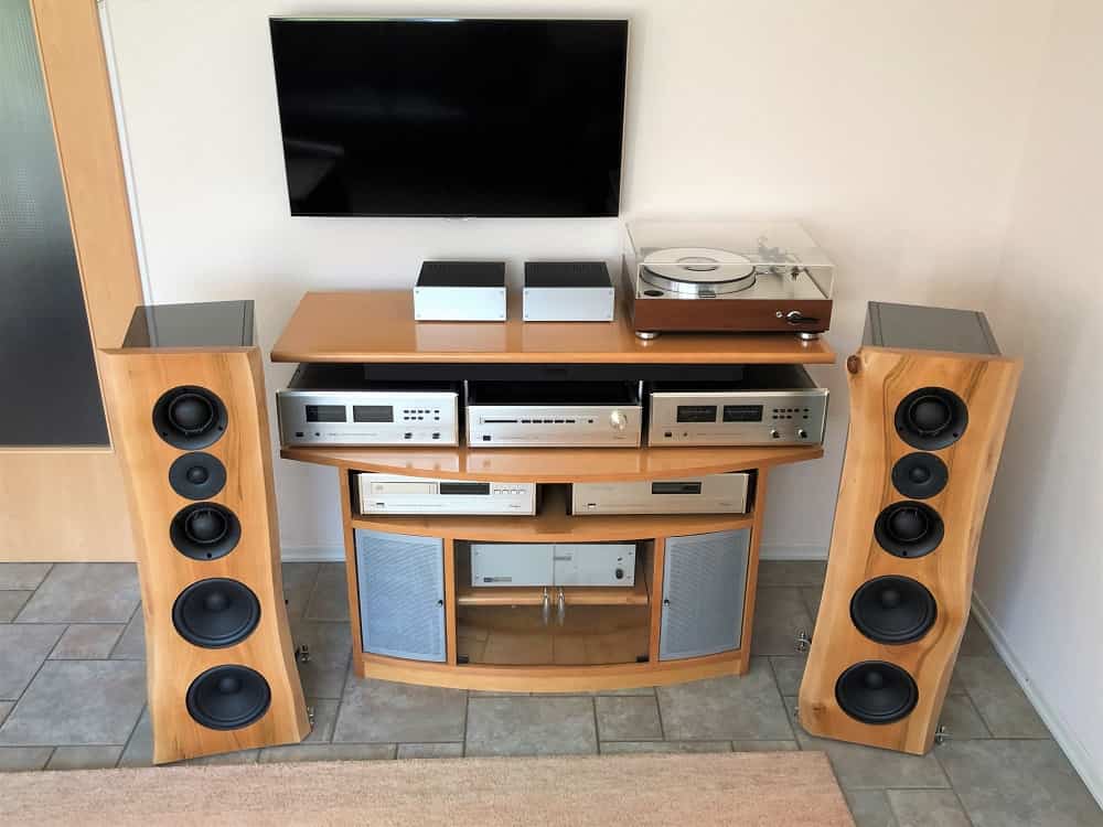
XOno complete
with power supply
Meanwhile I have routed new motherboards:
The power supply has migrated to the motherboard as well. Just like the XLR part of the XOno. This saves some Time in the construction by lower wiring effort.
mainboard
MC mounted
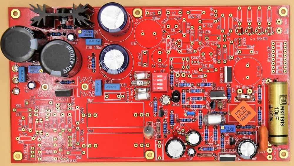
mainboard
MM mounted

Hauptplatine
not mounted
The rectifier board was also changed:
This received a three-stage (4.7mF, 10mF, 22mF) CLCLC screening. The values of the chokes used vary depending on the according to the current consumption of the variant.

rectifier-board
Top Side
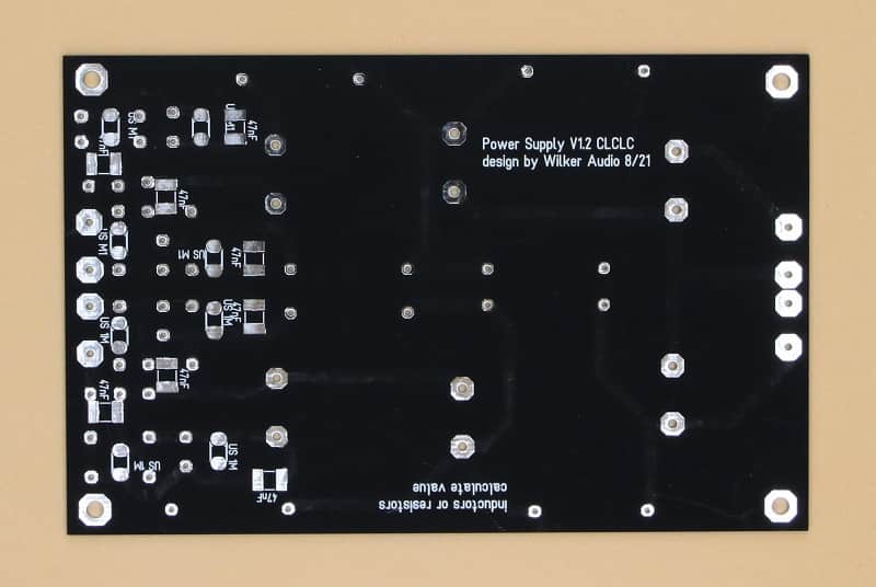
rectifier-board
Bottom Side
rectifier-board
full mounted
There will be another board to connect the transformer. This contains a DC filter and the connection protective earth/gnd of the power supply. The connection of the power switch is layed out for easier connection. For the Renovatio variant, a place for the power supply of the microprocessor is provided there.
New motherboards are also ordered. It is now possible to solder in RCA jacks directly. The C/R decoupling links are also on the board and no longer have to be laboriously wired by hand. In addition, there is the option to screw the Renovatio expansion under the main board and thus put it into operation.
All in all, this makes it much easier to set up a complete unit. Another page for building an XOno with the new boards will follow.
Downloads
Allow me to make one comment:
Since there are rude contemporaries who use even the smallest shred of documentation to use for themselves, no more schematics and layouts are offered here. If you need further information, please send me a short mail.
Buyers of boards or modules will of course still receive all the necessary data.

Write to me
Feedback

Warren´s version of XOno
from Australia
Xono up and running, thank you. It sounds amazing. Significantly better than the battery Boozehounds I was using.
Rüdigers Clone
from Fürth
Feedback: top!! Sounds very fine.
Stefan's XOno self made
the technology

private party
General view
Here is the comment from Stefan:
My expectations of the Xono have been fully met in any case. I have now listened to five hours of vinyl and I am as happy as a little boy about the great sound of the Xono. The sound is very clear, very detailed and very spatial, and the possibilities of adjustments and adjustments are almost unlimited.
The double bass by Ray Brown on the album Soular Energy (2 LPs 45 revolutions) stands like a rock and has multifaceted expression (it squeaks and buzzes in all variations) that it can't be much better live. With the live album Diana Krall Live in Paris (2 LPs 45 turns) the grand piano gets much more contour and it is now also the whole the mechanics of the grand piano. Even a soft coughing from the audience I have not heard before and I have I've heard it many times before. Also on the old Chris Rea record, Auberge, the stepping away of the bottle in front of the restaurant in the intro now sounds much more natural and spatial. I am very satisfied with the Xono.
Now let's get back to the prehistory, I used my Luxmann PD 300 with Denon DA-407 tonearm and Dynavector XX2 MKII pickup on my Accuphase C222. 4 years ago I tuned the phono preamplifier as well as the output preamplifier of the C222 with expensive NOS Black Gate N (bipolar) capacitors from Rubicon, which improved the sound and especially the space. But the XONO sounds much better to me than the tuned Accuphase C222 preamp.
Frank, I would like to thank you very much for developing the XONO as a DIY kit and giving us the opportunity to build up or purchase a very good phono preamp for a very fair price. I also found it very helpful that you accompanied the whole project and are always available as a contact person, even if I as a layman sometimes asked stupid questions.