The preamplifier module with Muses 72320/72323
Realisation by Frank Wilker
This project description will be further supplemented!!
last change: 2023-09-10
- design by
- Frank Wilker Audio-Perfect.de
- posted on 31. August 2020
Description
This adaptable input control will be a modular component that can be easily integrated into an existing power amplifier or a preamplifier. Likewise, use as a stand-alone preamplifier is possible..
The module offers the following options:
- Inputs: max. 4 x balanced, min. 1 x RCA (Cinch), variable mixable
- Outputs: one each RCA and XLR
- Muses 72323
- can be split between inputs and muses regulation
- Multi-channel capable
- Inputs: maximum 4 x RCA (Cinch)
- Outputs: once RCA
- Muses 72320
- Remote controllable
- Any existing remote control can be integrated
- Standby operation
- 2.6 inch TFT colour display
- Volume and balance control
- Stand-alone capable (passive or activ PreAmp)
- Mains voltage switchable as output (8AA)
- Trigger output in 12V or 5V
- Smartphone capable (under consideration)
- Bluetooth (under consideration)
balanced board:
unbalanced board:
common features:
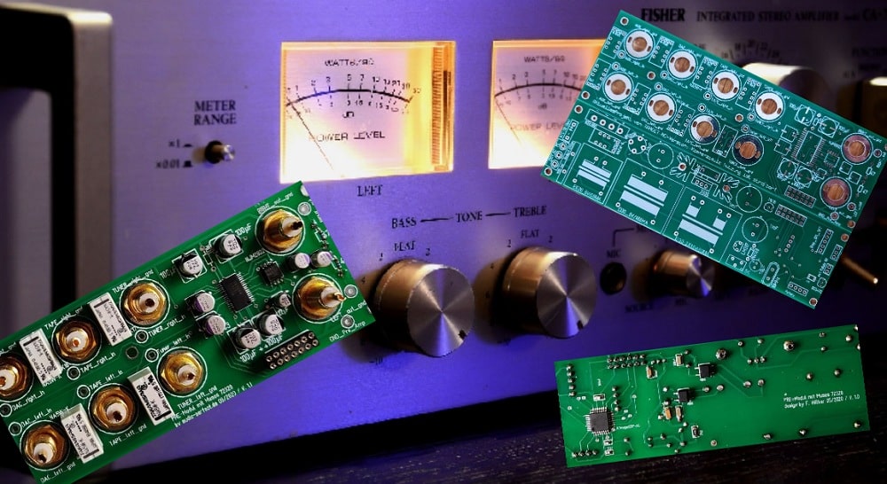
The technology
Signal-Platine
5 Paar Cinch-Buchsen
Steuerzentrale

Signal-Platine XLR
Bestückung siehe Text

Steuerzentrale
Netzteil/Mikrocontroller
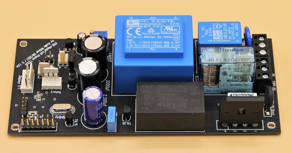
The technology is housed on two separate boards. The power supply, microcontroller and the connections for the signal board signal board, IR sensor, rotary encoder and the 2.6-inch display are on one board.
The signal boards contain the input and output connectors, the relays, eventual OPAmps (OPA 1656) and the Muses chip for volume control.
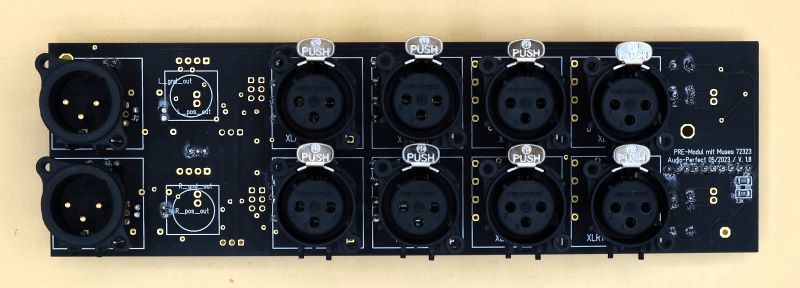
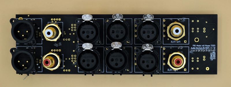
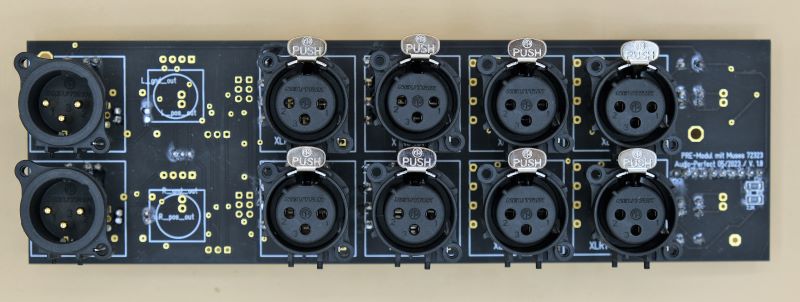
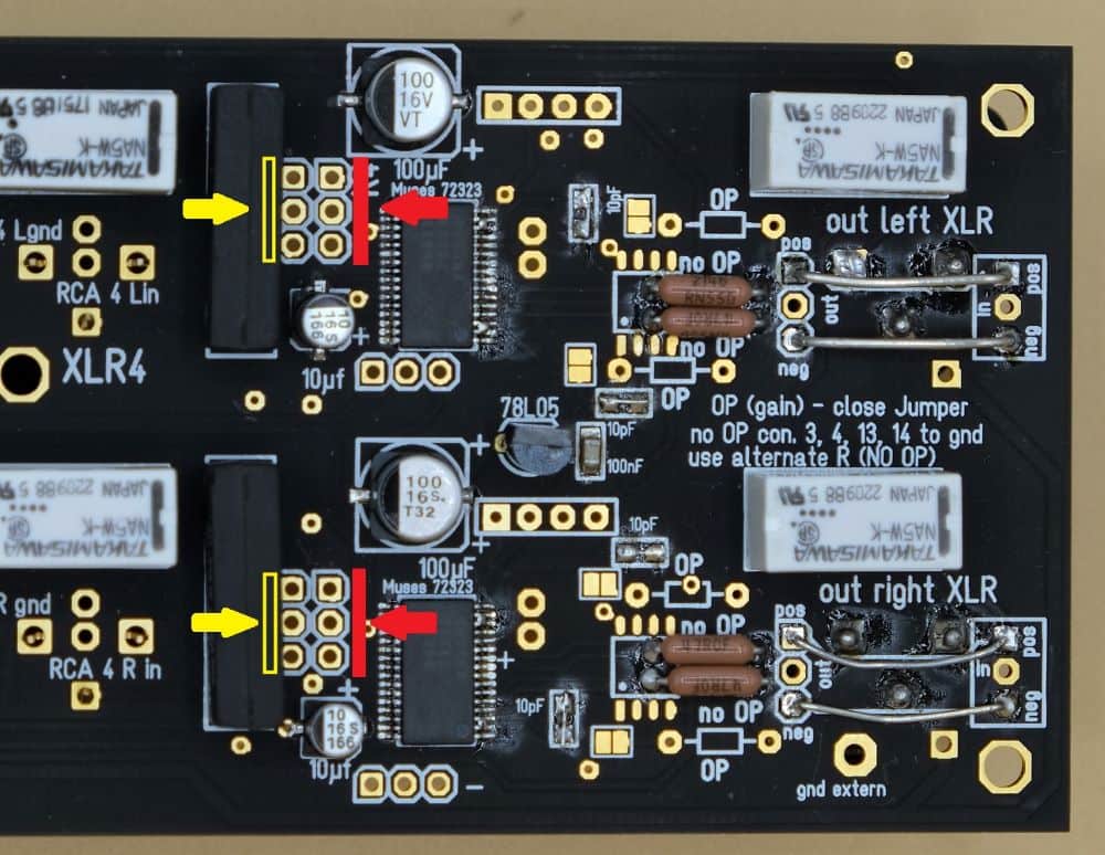
The balanced (XLR) Signal board:
Signal board XLR
many possibilities
Signal board XLR
Mounting see text
Signal board XLR
XLR equipment only
This can now be equipped with a total of 5 inputs. One of these inputs must be wired as unbalanced. unbalanced. The other 4 inputs can be equipped as RCA or XLR inputs. Logically the board now contains two of the volume chips: Muses 72323. One RCA and one XLR output each are available as outputs.
The board has a variable design and can also be operated "only" in unbalanced mode.
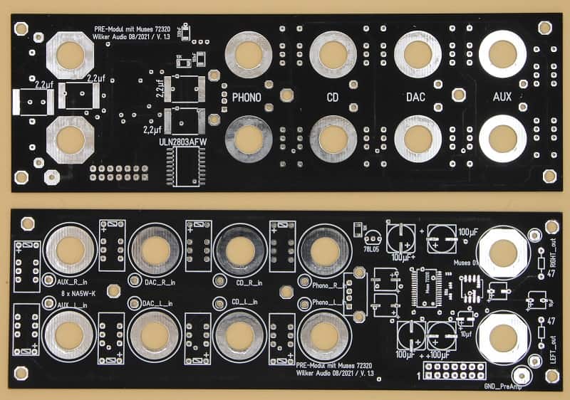
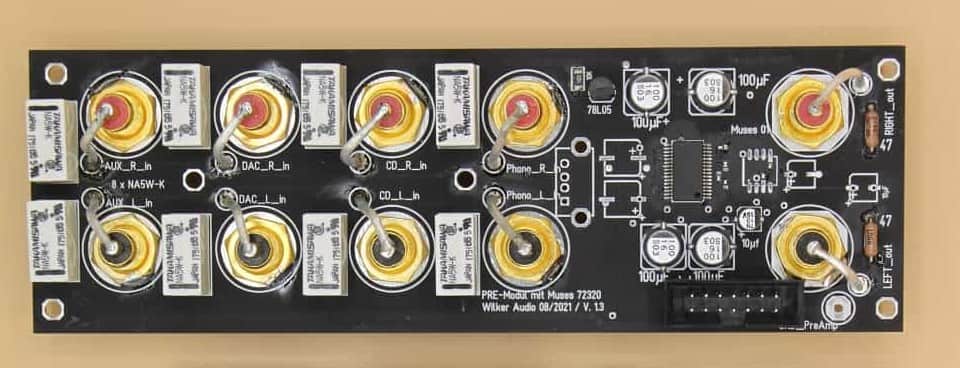
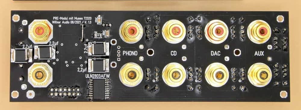
The unbalanced (RCA) signal board:
Signal board RCA
4 x In - 1 x Out
Signal board RCA
Film caps
To put it in advance: The boards are NOT equipped with coupling capacitors. Picture 2 is an old photo of a test version.
Four inputs and one output are possible with this board. Except for the multi-channel possibility and the splitting of the signal signal between inputs and volume control, all functions are identical to those of the balanced brother.
For this board I had used cheap RCA jacks for cost reasons. By soldering the construction was nevertheless stable and of high quality. You can of course wire the inputs and install "higher quality" jacks.

neue Bilder
5 pairs of RCA sockets

Signal board
NEU NEW
MP Platine
with PS
The old design required either installation behind the rear panel or additional wiring of the inputs. The new solution uses the input and output jacks as holders. The sockets each have stable screw connections, which are screwed to the rear panel.
Weitere Features:
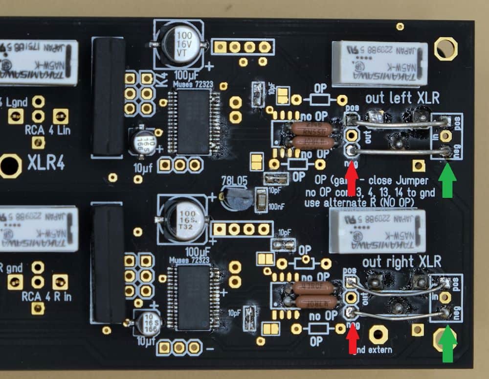
It is possible to take the input signal BEFORE the Muses chip and process it further. For this purpose there are solder pads/pin headers to which the signal is applied. A DSP can easily be looped in here.
Additional Muses boards can be plugged in using the sandwich principle. This makes it easy to build up a multi-channel system. The additional outputs must then be wired externally.
I have also provided space in the layout for an OPAmp. This can provide an additional gain of up to 21dB. available. Customers with Class-D power amplifiers had asked for this extension, because the output voltage of conventional devices is too low for full modulation of the output stages.
If no amplification is required, the OP can be omitted.
Since I now use a port extension (I2C), the number of connecting cables has decreased significantly. The annoying ribbon cable has given way to a flexible 10-pin cable.
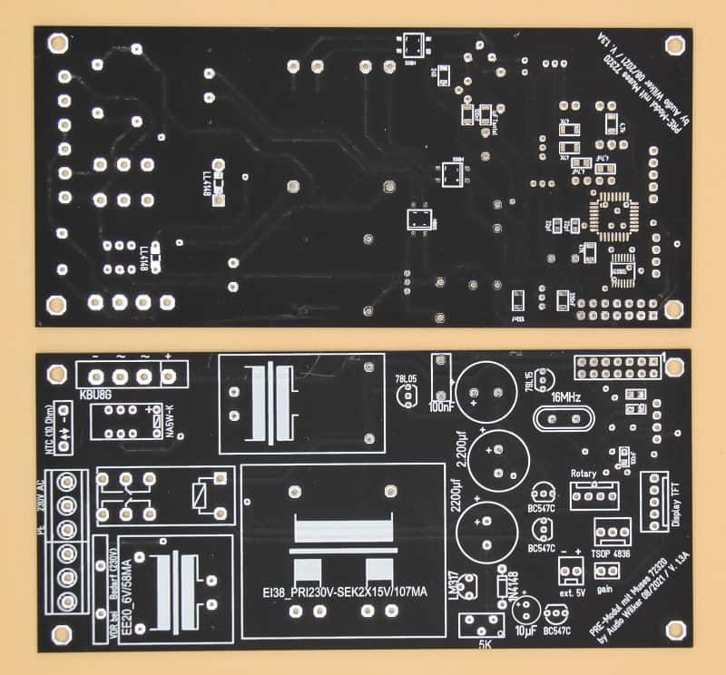
Microcontroller board
Microcontroller board
load instructions
The entire hardware is again controlled by the Atmega 328p, which has already proven itself in several projects.
The control board contains the entire power supply. The module can be operated in standby mode and can be switched on and off by a remote control. on and off by a remote control. The used HiLink has a power consumption of approx. 200mW in standby mode.
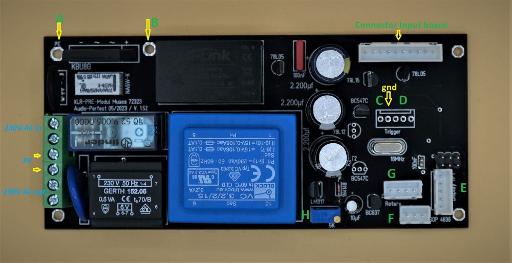
The trigger output can output either 5V or 12V. It switches on 3-4 seconds after the module is switched on. With this external power amplifiers can be switched on.
The relay output (8A) can be used to switch the mains voltage. The output of the mains voltage is available at a PCB screw connector. This output is switched simultaneously with the trigger output. This output is intended for operation as a full amplifier.
A 10-pin connector transmits the control signals and supply voltages to the input board. On this way the Muses chip and the input relays are addressed. The relays disconnect the input signals completely from the subsequent circuitry. So there is no ground problem here due to undefined ground connections or loops. Also Pin1 of the XLR inputs is also disconnected.
The digital control signals to the Muses chip are processed by a digital isolator. Analog and digital voltage supply are thus perfectly separated.
In addition, three further control signals were led out, which could be used for external actuators. If required, this could be integrated in the software.
As a further feature there is a connection between PE conductor and gnd on the MC board. This is formed by a rectifier and an NTC. This effectively prevents hum problems.
The construction
Signal board
passiv Preamp
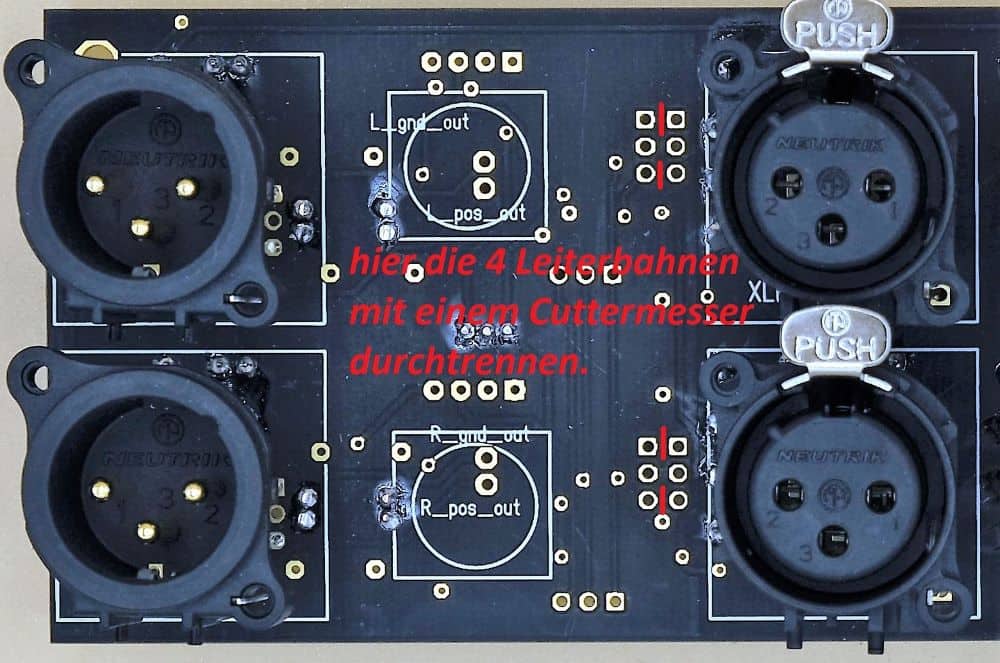
Signal board
cutting traces
Signal board
loop in DSP
The signal board contains 4 balanced and one unbalanced input. All balanced inputs can also be used can also be used as unbalanced inputs. Both variants are available as outputs.
Behind the output of the Muses-Chip the signal can be taken and fed into the following amplifier electronics. electronics. If you use the module for a preamplifier, the output signal is applied again before the output sockets. Pin headers or solder pads are available for this purpose.
In the simplest case you connect these pads and get a high quality passive preamplifier without the need for further electronics. If you use the gain function of the Muses chip, it even becomes an active preamplifier.
Naturally, the module can also be used to build a full amplifier. These output sockets are then not populated. Or you use this as an output for a subwoofer or similar.
Since there are no coupling capacitors in the signal path, this can lead to unpleasant noises when switching on or off, depending on the connected electronics. when switching on or off. For this reason, the time until the mute relays are released can be extended during the power-on process. during the switch-on process. This time period can be set in the software.
The operational amplifier (OP/JFet) provided on the circuit board is only used if the gain function of the Muses Chip is desired. This is able to control an OP directly. If this function is not needed, it is sufficient to change the output resistors differently.
The Software
The proven software of the SAP (Stand Alone Poti) was taken over and extended by various capabilities. Added was of course the input selection. The input is shown in the display. Additionally there are now more IR codes for input selection and for the standby mode are available.
Digole 2,6 Zoll
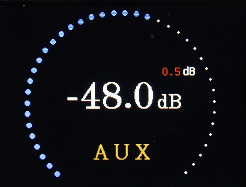
Main Screen
The volume is shown in dB in the center of the display. The white ring consists of 35 dots, which are filled in proportion to the selected volume in blue. to the selected volume in blue. The selected input is displayed in the lower third. The display can be The display can be changed in some points in the options menu.
Again, I went back to the proven concept of one-button operation. With this concept I always have in mind that the operability should be intuitive.
The operation
Let's move on to the pushbutton of the Rotary Encoder. The print length determines the subsequent operations. The selectable options are are shown one after the other -> Balance menu -> Options -> Standby. Doesn't sound like much choice, does it? Wait and see.
A short press takes us to the input selection (or alternatively to the mute switch). Now this reads a little tricky, but it explains itself during operation.

Mute
After a short press, the Muses chip is set to mute mode and the previously used input is displayed in green. displayed. If I now remain idle, the icon for Mute is displayed after approx. 2 seconds. If I want to change the input, I can select it within the 2 seconds by selecting the corresponding input with the encoder. with the encoder. By turning the encoder, the selection time is stopped at the same time, so that enough time is available for the selection. is available. Once I have found the desired input, I simply wait. The new selected input is switched on after 2 seconds switched on and the volume is gently ramped up.
If I had triggered mute with my button press without wanting to change the input, I can return to music playback by pressing the button again or turning the encoder. or turn the encoder to return to music playback. This also works with the remote control.
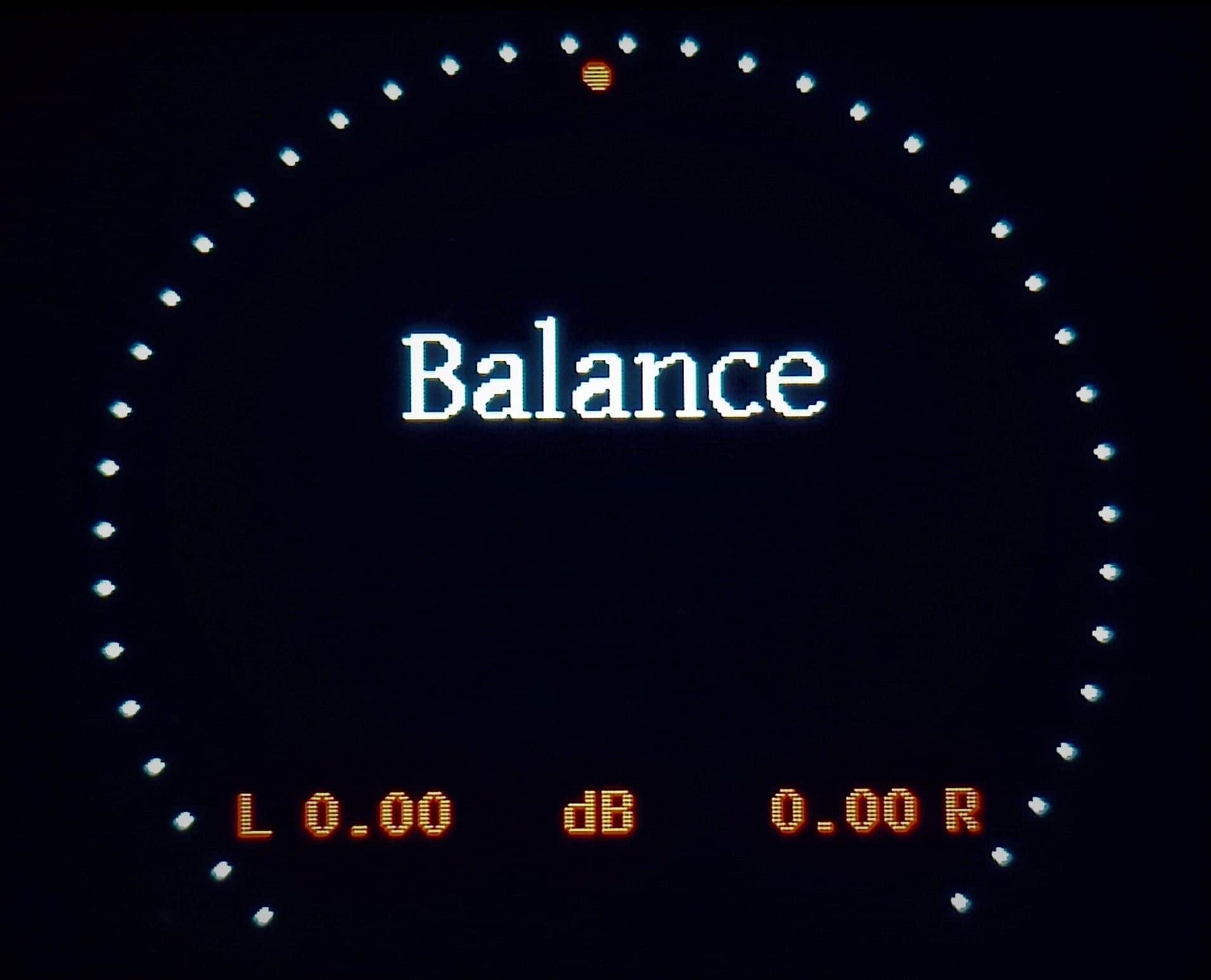
Balance Menu
After pressing the button for approx. 0.5 seconds, the balance menu appears. If the button is now released, I am in the balance menu. The balance can be changed by turning the encoder. The balance control works in 0.25dB (Muses 72323) or 0.5dB steps. The respective value is displayed at the bottom right or left. The red dot visually indicates the current setting. Another keystroke saves the setting and returns it to the main menu.
Halte ich den Taster für ca. 1,5 Sekunden gedrückt erscheint das Optionen-Menü.
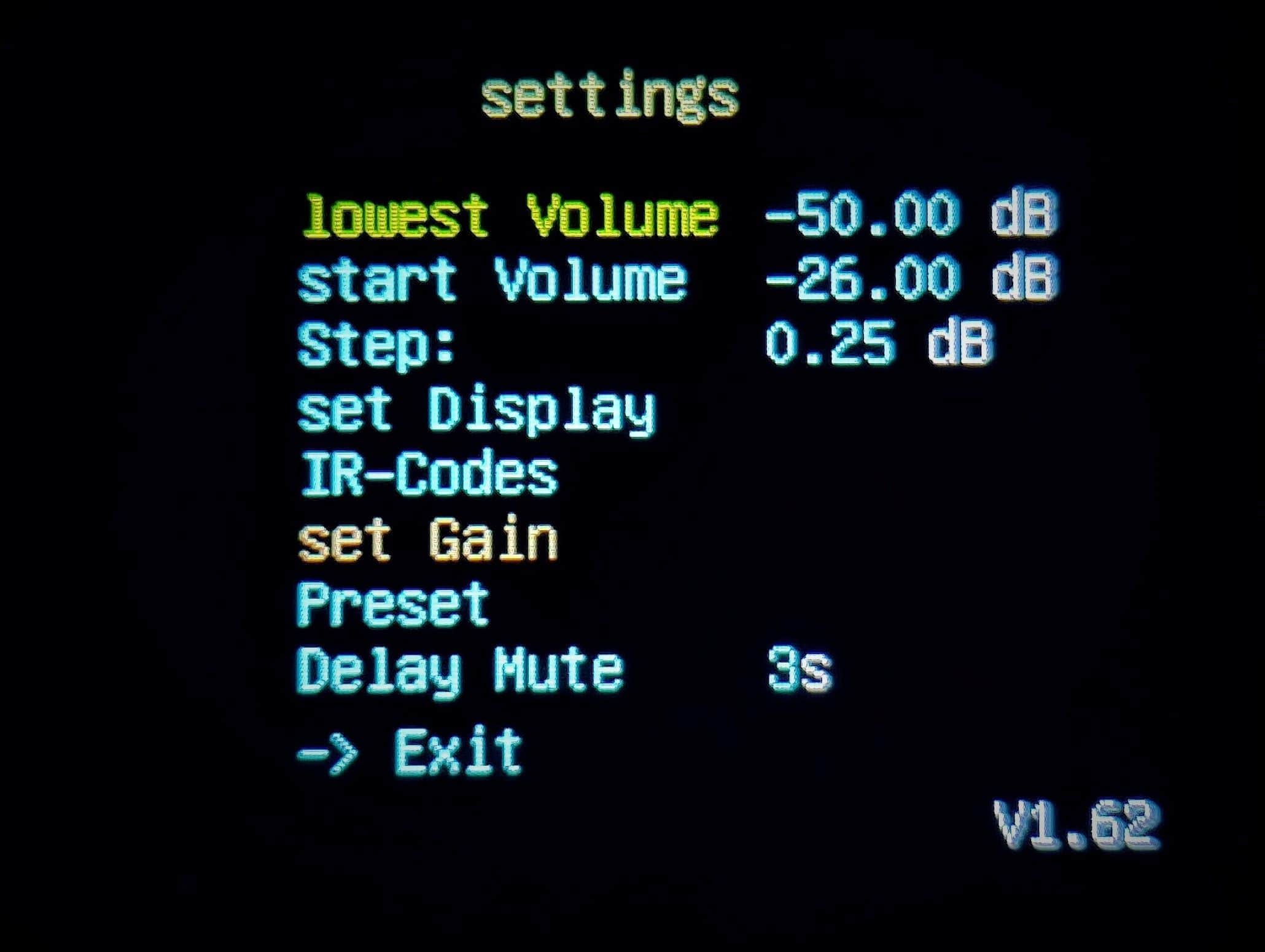
Options Menu
The following choices are available here:
- lowest volume
- start Volume
- Step: xx dB
- set Display
- IR-Codes
- set Gain
- Preset
- Delay Mute
- -> Exit
Turning the encoder will "highlight" an entry. Pressing the button selects the corresponding entry. selected.
I don't want to make this page unnecessarily bulky by explaining all the menu items. Under Downloads you will find an explanation of the available options. Most of the functions are self-explanatory.
Options Menu
settings
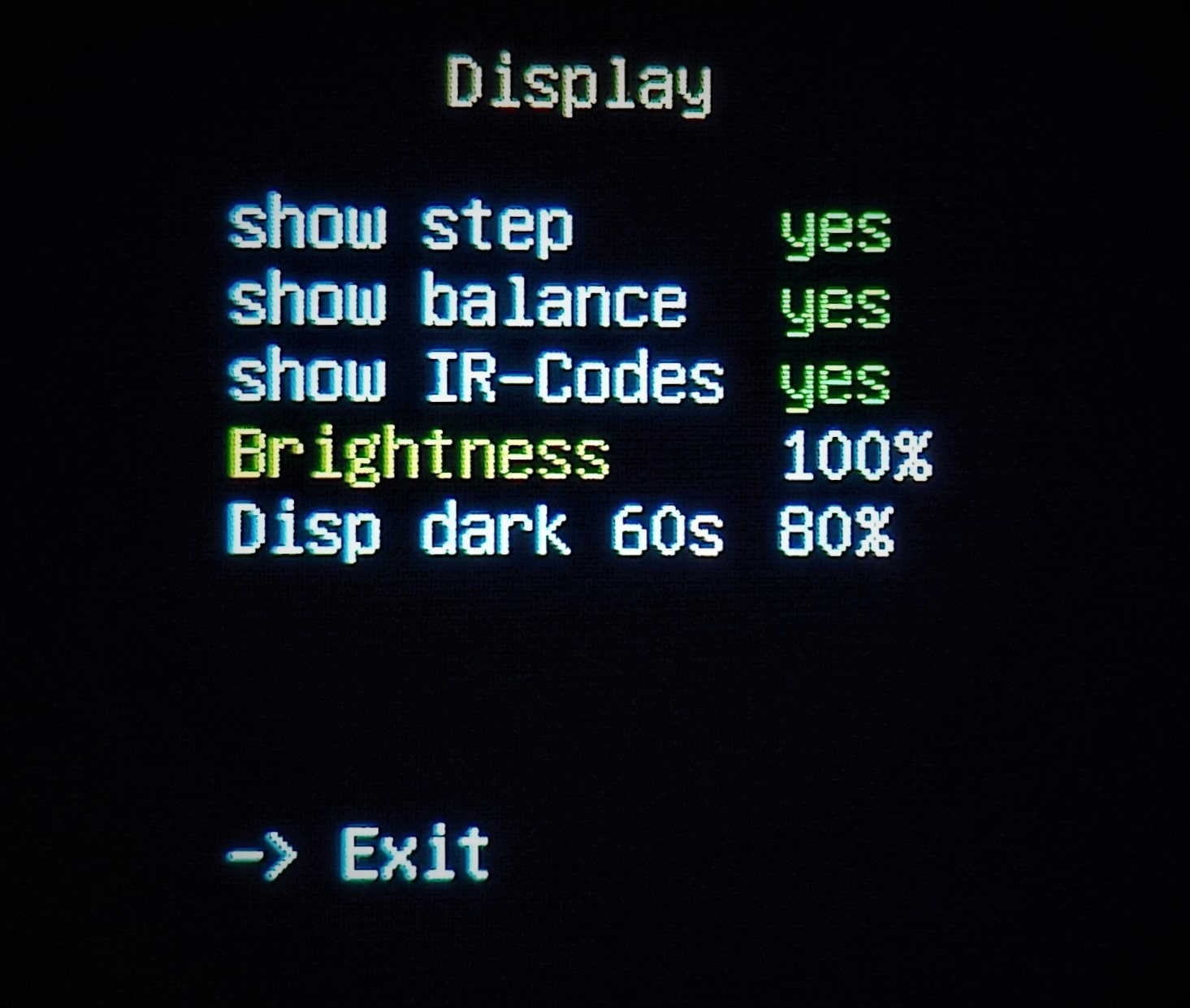
Display Menu
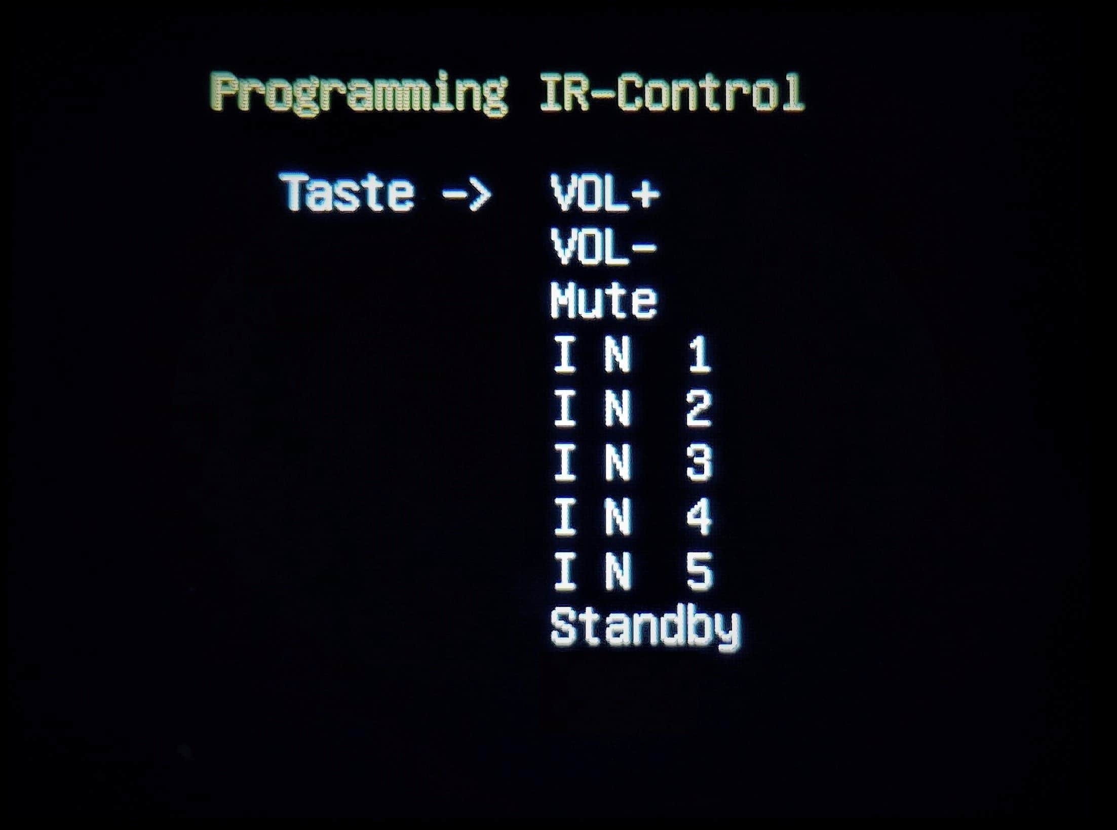
Remote Control
Programming
Standby Mode
If I keep the button pressed after the options menu appears, the message "Standby" appears in red. After releasing the button, the module is set to standby mode. The signal is smoothly shut down; the external outputs and the trigger signal are switched off. The display is also switched off. Finally, the analog power supply on the MP board is switched off. Now the module consumes less than 200mW.
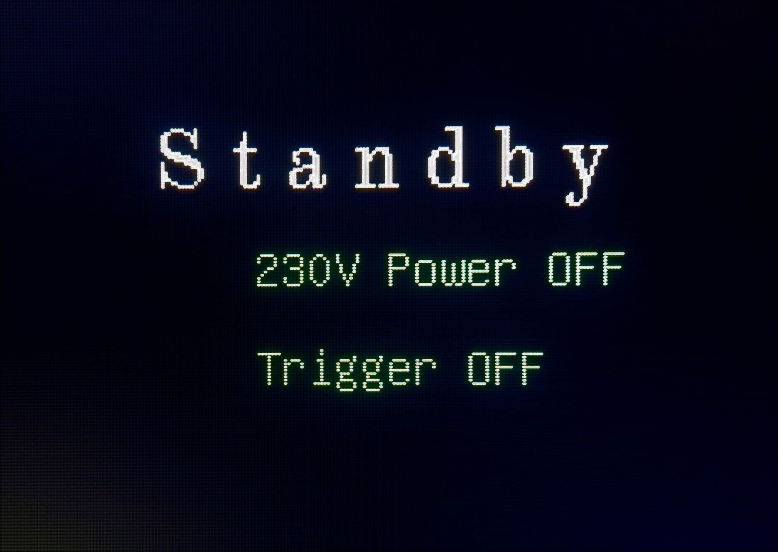
StandBy
mains voltage/ Trigger
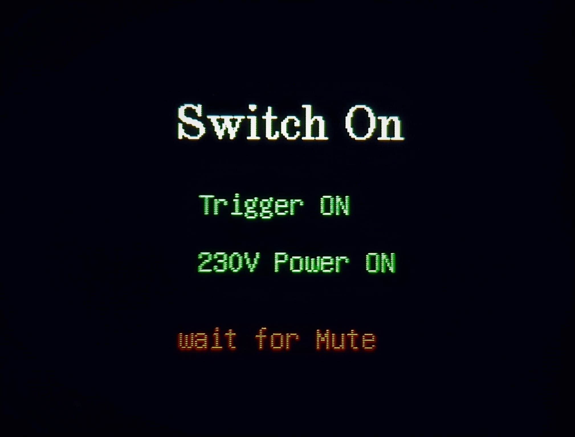
Wake Up
Mute adjustable
The module can be switched on again with the remote control or by pressing the button again for a longer time.
Remote Control
The Pre module can learn the signals of most (also Apple) remote controls. There is a separate menu item for this. The remote control can be used to select the inputs, control the volume, mute and standby mode.
An example of installation
There will be a section on the construction of a passive preamplifier here in the next few weeks.
Updates
No standby transformer is used anymore because the HiLink used is so efficient in standby that it consumes significantly less than the standby transformer in operation (200mW).
In addition, a solution with OPA1656 and subsequent BUF634A is in progress. This reduces the output impedance and thus the influence on subsequent devices is considerably reduced.
Downloads