Digital volume control Muses 72320/72323
Realization by Frank Wilker
project ended: 18.01.2021
- design by
- NJR Mystic Jewel of Sound
- Ver. 1.1E
times again why
A digital potentiometer? What's the point? And then in the high-end world I'm supposed to be moving in!
My research has uncovered several variations:
- Poti-coal layer
- Poti-high quality
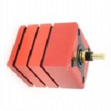
- Motor pot
- resistance array switched by relay
- Switch with single resistors
- Poti conductive plastic
- Digital chip
The coal layer
The blue Alps
audiophile rotating feeling!
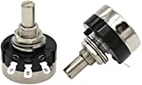
The conductive plastic pot
minor deviations
Highlight of Khozmo
more than 300 euro;
What is what?
And how good is which variant? Of course the net offers a wealth of information. As we all know, lurking there numerous traps. Many statements are subjective and not comparable. We know how it is. The amplifier so praised is listening bad at home...
standard
Coal layer pots
The coal layer pot deviates sometimes 20%, scratches audibly in the course of time and is available for under a Euro.
The high-quality potentiometer; which one was there? I fondly remember these sluggish turning pots: The blue Alps is so one. Also not that expensive, around ten euro. Except for the audiophile rotating feeling, that's how it is advertised, it corresponds to the carbon layer pot. The processing is clearly better, but the deviation can also be up to 20%.
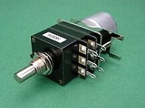
The motor pot is the one just described with the same handicap. Costs around 40 euro.
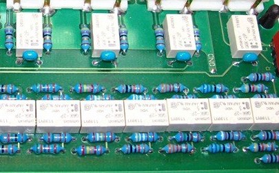
Resistor-Array
relay-switched
Continue with the resistance arrays. We're already into a very complicated area here. We need a microprocessor to control the relays. We can determine the resistance values and thus also deviations ourselves. Our signal must be routed through the relays. So we need high-quality types and high-quality resistors. Provided the MP is reasonably shielded, I would qualitatively place this variant at the top end of the scale. A disadvantage are the constantly clicking relays. For those who are laughing now: there are some owners who find it quite annoying.
Switch
24 steps
A switch with single resistors forms the variant of the resistor array without microprocessor. But you need high-quality tap-changers. Otherwise you have a noise in the boxes when switching. So also not quite inexpensive. But you are welcome to try the cheap variants from China. I bought them once. Then unfortunately you buy twice.
Now we are at the pot made of conductive plastic. Here the deviation of the synchronisation is about 1%. That is already very good. The deviation of the resistance value is unfortunately also up to 20%. In the potentiometer SMD resistors are used, which are connected via conductive plastic conductor path. Here at least the switching noise is omitted. Unfortunately the quality of the resistors not to be influenced. These potentiometers are also available with motor. The prices are between 50 Euro and 250 Euro for very noble types.
Now the digital chips. This one is controlled by a MP, has mostly very good technical values. Also here there are 1. different manufacturers and 2. different statements about the quality of the individual chips.
Motor-Pot
The electrically operated potentiometers, the relay arrays and the digital volume controls have the additional advantage of Remote controllability. At the time, I was building up a pre-publisher of the magazine �Elektor". Here was also a digital Pot installed. The pre-recorder was also quite good, but didn't knock me off my feet. However you could operate this device very comfortably. The adjustment of the channels for signal sources with different volume levels was just as little a problem as switching or silent turning.
Since you are reading these lines, you have already collected information about the Muse 73230. What made the difference for me was this, very often made, statement: "I haven't heard it better yet." or "The best volume control, I have ever heard". These were the statements of people who had installed this chip somewhere, or owned a device with a built-in Chip. There are of course also many statements against it. "Why should this chip be better? The chip from XYZ has almost the same data..." or "The digital potentiometers can all do the same thing!" However, the critics all had in common ...that they had never heard the Muses chip before!
When I then checked for fun in which commercial devices this chip is built in, my decision was fallen. He works in the flagship amps of the high-end guild. So it became Muses 72320.
Muses 72320
ready for evaluation
If the question arises, if this board is not already available, I would like to answer it as well: There is a provider in the USA. Not quite cheap. In the DIY forum there is someone who sells boards with MP. But he did not follow the Requirements of the manufacturer to install an OP-Amp at the output. And I absolutely want to follow the data sheet. This always makes sense. There is/was another supplier in Japan. Unfortunately this one is not available at the moment. And besides I have the ambitions to provide this chip with an input selection and a reasonable display, so that you get a module, which can be integrated into other projects without much effort!
After I had just routed a board, ordered three of these noble chips and programmed them, this project stagnated, because other projects demanded my full attention.
Then Uli came along
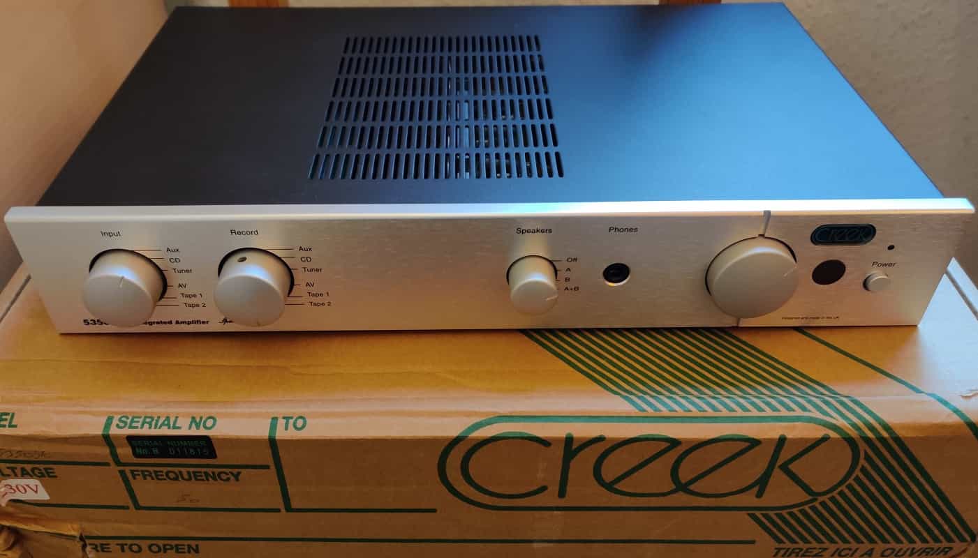
Uli bought a preamplifier and some line filters from me. He got a little tip about a nice MM-System and then asked again briefly whether I could repair the scratching pot in his integrated amplifier of the Creek company. You already know what it's all about. I didn't have the amplifier in my hands, but advised him to upgrade when ...you change the potentiometer anyway. A mail with my ideas, here also the term Muses 72320 appeared shortly, let Uli in the certainty that it would become the Muses.
Dear Uli, I couldn't find the circuit board I bought once. That's how I have my other Projects somewhat postponed. A board for a stand-alone solution is ready routed and also already ordered. The software is already programmed in the individual parts -volume control - IR reception and storage. Now we still have to bring everything together on a development board. And it still has to be tested.
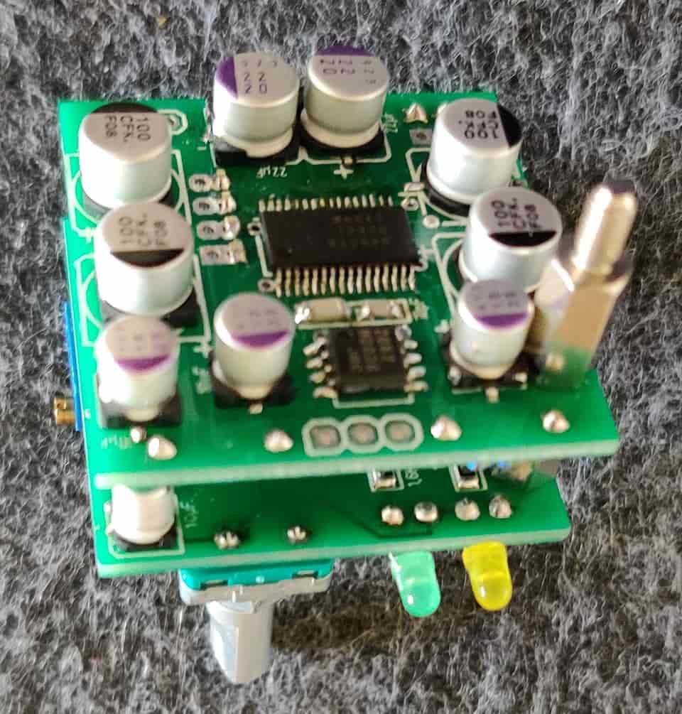
The Hardware
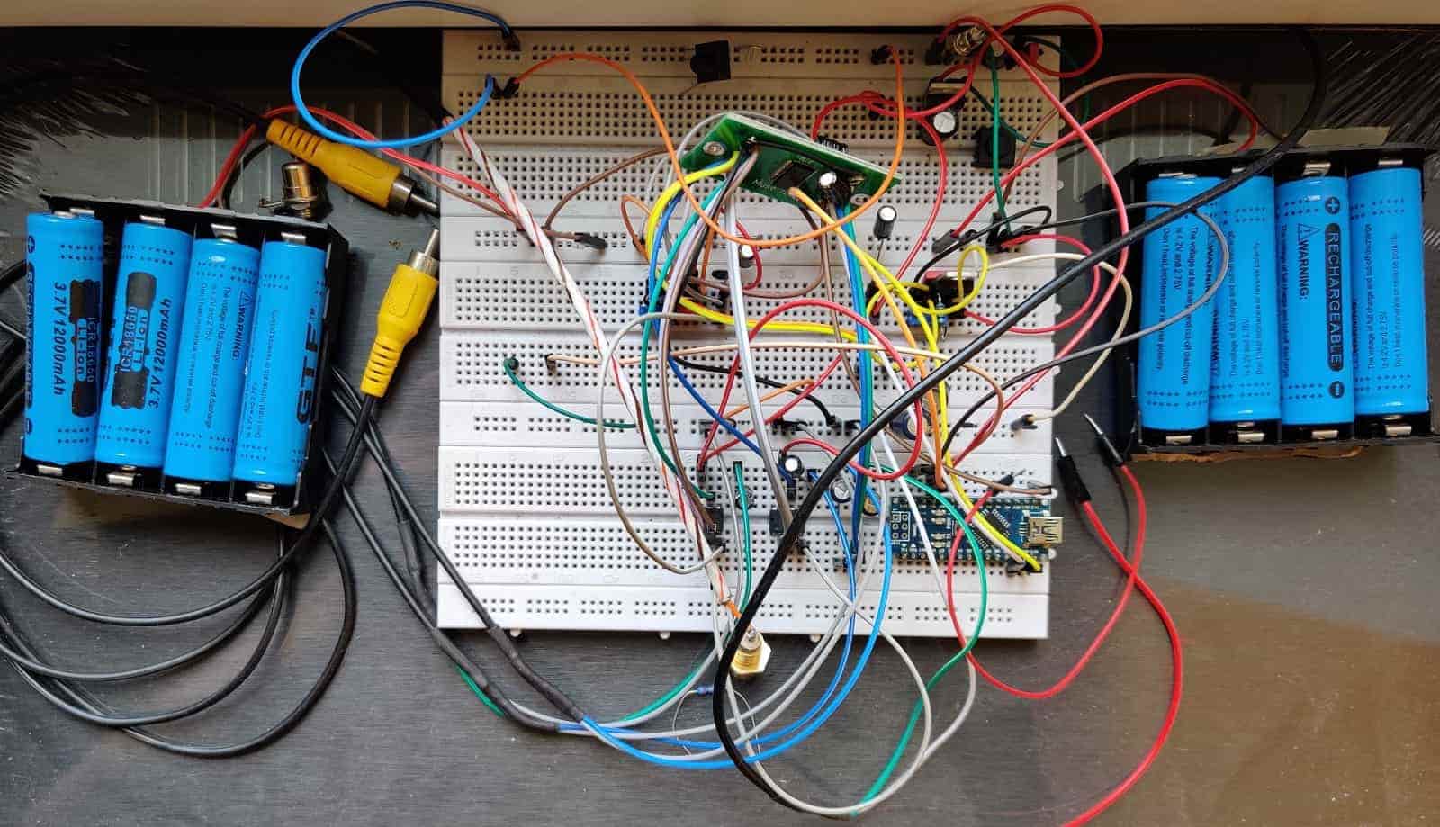
Development Board
still without IR Sensor
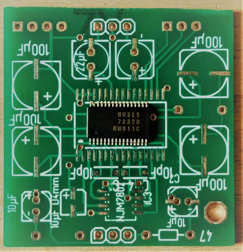
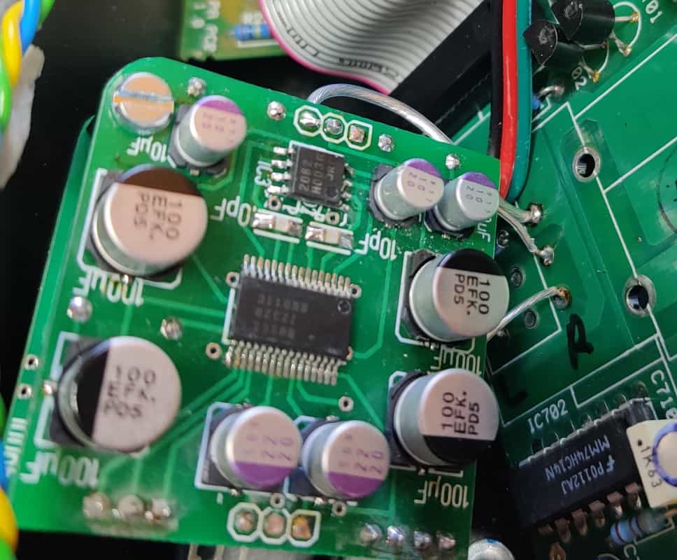
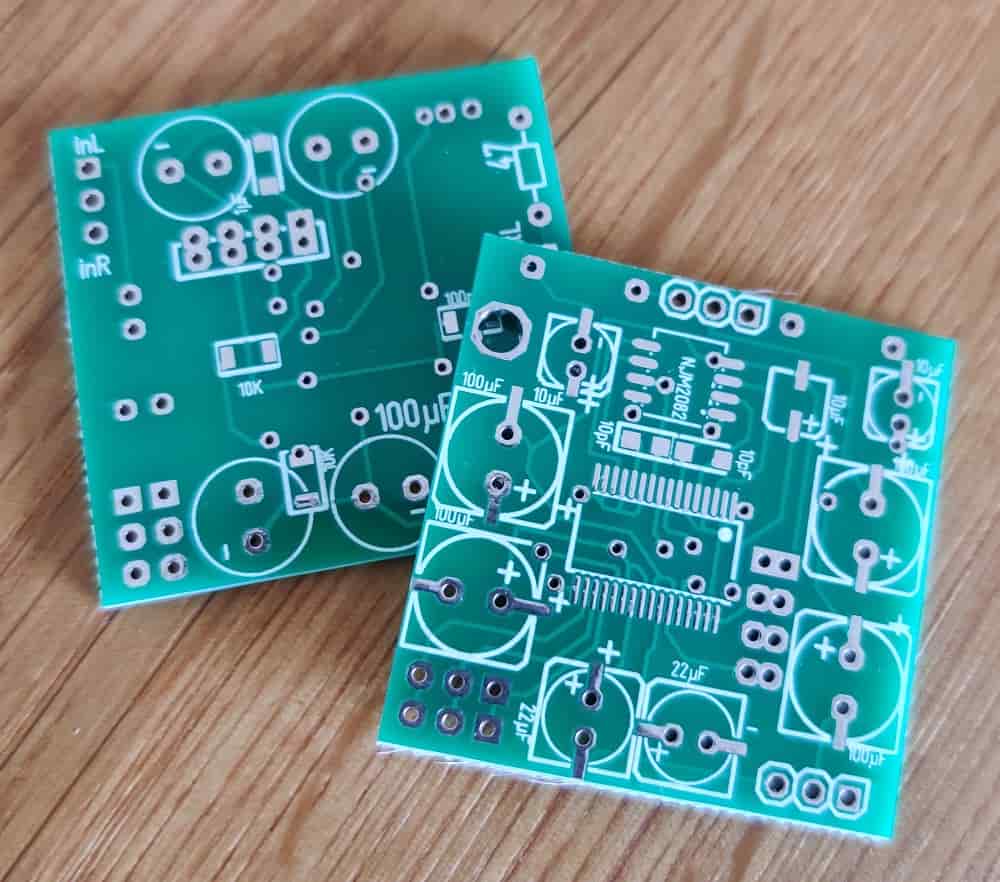
I have completely adhered to the data sheet of the Muses Chip. And here is an additional operational amplifier (OP) provided for. The circuit board corresponds to the circuit proposal of the manufacturer. The OP-Amp is a NJM2082 from Muses. This is still well available and acceptable in price. Of course a replacement type can be used here. Otherwise there is still space on the board for some decoupling and coupling capacitors.
With this the board (40x40mm) is then also well filled. There is also a four pin connector for the power supply, two three-pin connectors for input and output and one connector for the SPI port on the board space.
Now all we need is a microprocessor (MP) and a rotary control for controlling the 72320. The MP reads out the signals of the rotary controller (incremental encoder or also called rotary encoder) and passes them on to the Muses 72320. To make it a little more comfortable, I also provide a connector for an IR receiver. The digital signals of such a chip can be easily decoded. The addition of remote controllability by any remote control does not present a problem.
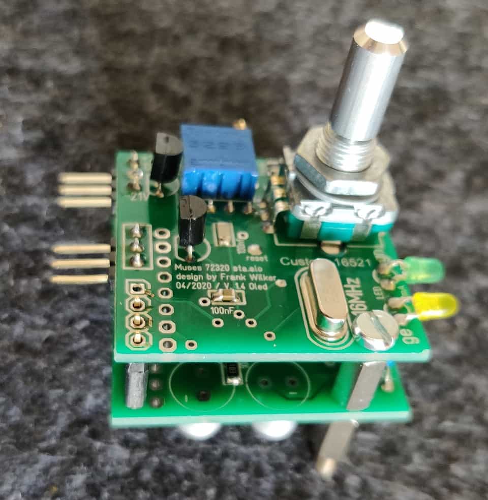
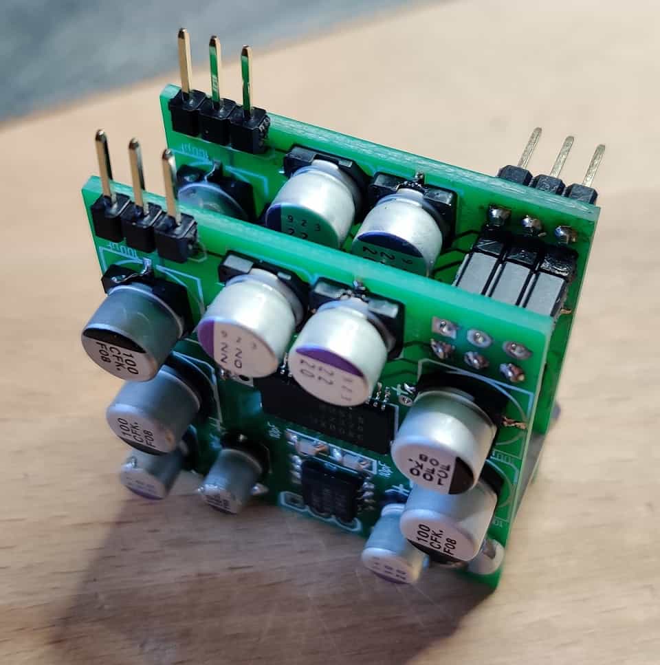
Now only the power supply is missing. The Muses Chip needs up to +/-18V and additionally a 5V voltage for the digital part. The MP also needs a 5V voltage. Since the stand-alone solution should be mountable like a potentiometer, I have a sandwich construct in mind. That means we have a board with the power supply (at least the control), MP, encoder and various plug connectors. There the circuit board with the Muses chip is plugged on. Through the connectors and an additional spacer bolt, the whole construction becomes very stable.
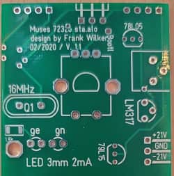
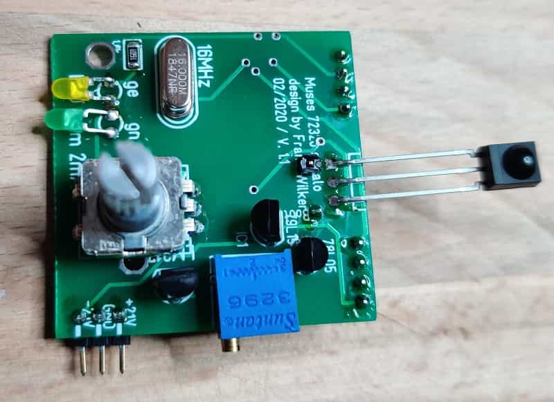
Power supply unit
with Encoder
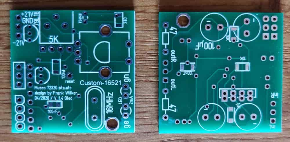
The power supply consists of a fixed voltage regulator for the 5V voltage, a voltage regulator (also fixed) for the negative supply voltage and an adjustable voltage regulator for the positive supply voltage. Why am I not using another fixed voltage regulator in here? The output voltages of a negative and positive voltage regulator differ very strong depending on type. The voltage difference can be more than 1 V. I would like to avoid this. So I measure the negative supply voltage and set the positive voltage accordingly. The 5V voltage is obtained from the 7805 behind it. As supply voltage for the Muses 72320 I have planned +/-15V. So a 7915, a LM317 and a 7805 are used for the Cue. The circuits are wired according to the data sheet.
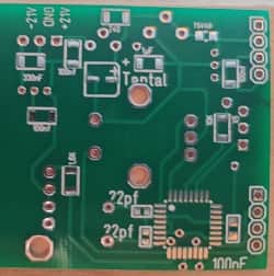
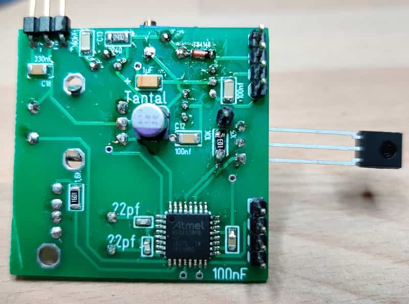
Connector side
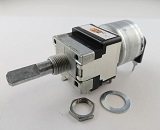
with microprocessor
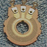
As MP an Atmega328 is used again. The IR receiver should be a 36 kHz type. I used TSOP4836. Attention: Other types may have a different circuitry. As encoder I use a special type of Alps. This one sends 24 signals per revolution and has an additional button which can be used for programming.
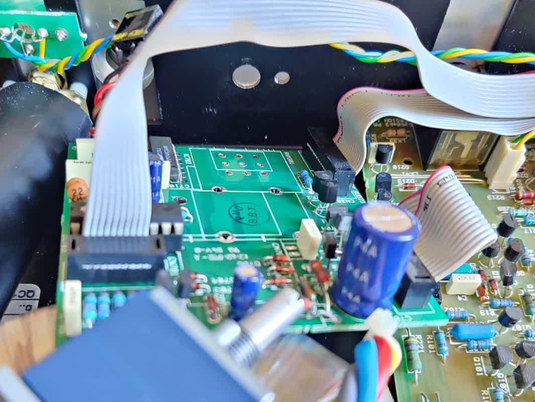
Luckily, I took another quick look into the creek that should receive the first potentiometer. The device is very narrow. To remove the board, on which the motor potentiometer was mounted, I had to already remove the toroidal transformer.With 40mm height I get my stand alone solution (I call it now briefly SAP = StandAlonePoti) also not built in. Either I moved the circuit board of the Creek, which appears impossible due to the density of the device. Since there is still some space left at the top and sides, I move the encoder to the edge of the Circuit board. This should solve the problem. So I already have two different versions available.
One more word about the power supply: As input voltage for the potentiometer we need at least +/-17,5V (maximum +/- 37V). Normally you can get this voltage from the power supply of the amplifier. If this is not possible, we need a transformer with rectification and unregulated symmetrical output voltage as described above.
Connector side
with microprocessor
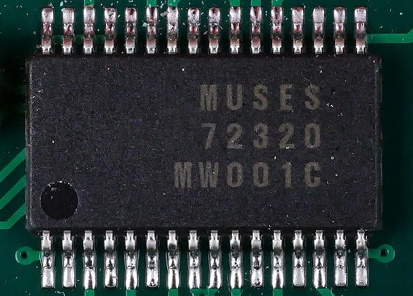
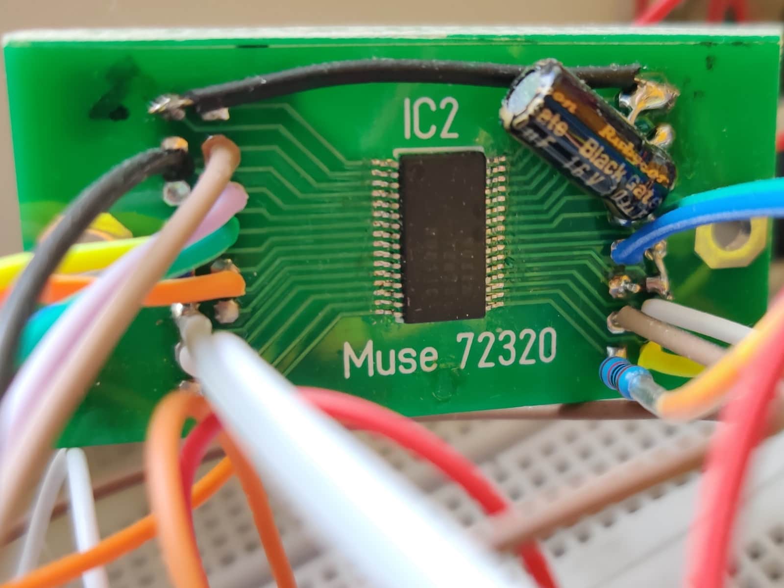
And here's a small example of the bugs in the development stage that can throw you back a few weeks:
After routing the board I always check if the available components are aligned with the board. Since for the Muses chip in the software there was no case available, I had to "rebuild" another SSOP32. Unfortunately, I then later did not use the "converted housing" but the output version. The result (picture) speaks for itself.
So quickly re-routed and also ordered again. And again it means waiting!
The construction
The time for waiting is over. Let's get active!
Please proceed as follows:
- Checking whether the existing components correspond to the layout
- SMD resistors and capacitors (small) by form factor (smallest components first)
- Microprocessor
- Elko
- SMD resistor top
- Voltage regulator, potentiometer and quartz
- LED so that this direction can be bent around the edge of the board.
- Rotary encoder
- Connectors, if desired or required
Board with MP:
Proceed as follows for soldering:
Power supply unit, Encoder
and IR sensor
Connector side
with microprocessor
The IR-receiver can of course also be soldered in directly. If it is at a more distant location of the front panel please use a shielded cable here as well. I also do not use a connector, but proceed as for the entrances and exits. One more little tip: The IR receivers can also be connected to the flat side to the front. These receivers are very sensitive and permeable to all sides.
- Checking the components as above
- Muses 72320
- Operational amplifier
- Resistors and capacitors (small) by form factor (smallest components first)
- Elkos
- Connectors, if desired or required
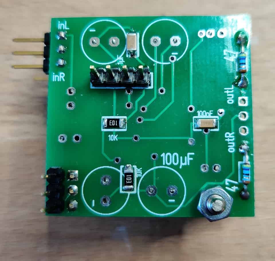
Board with muses:
Proceed as follows for soldering:
Instead of the connectors for the input and output I usually solder a cable directly. This connection is of higher quality than any connector. This should be made as the last connection, because it is likely to be very narrow due to the probably short power length.
Basically, it was. Now only the two voltages for the muses have to be measured and adjusted. We adjust the positive voltage with the precision potentiometer so that it corresponds to the negative (previously measured) voltage of the 7915. Now we put the two boards together for a test. Please bend the LEDs so that they can be seen from the side or can be observed from above.
If the boards are aligned nicely, only the spacer has to be screwed on. Now we solder the cables for the inputs and outputs. Before I check whether the length is sufficient to allow the SAP to be screwed into the front panel. This can then be done immediately. Finally the cable for the power supply is plugged in and the good piece is installed.
Now nothing should stand in the way of a successful function test.
The software
Now we come to the programming of the Muses 72320.
The MP interrogates the rotary encoder, its push button and the IR receiver. The incoming signals, which are all digital in nature, will be decrypted. Depending on the input signal the corresponding commands are passed on to the Muses Chip.
In the SAP version only the basic functions of the muses chip are used. Since no visual output is provided, these enhanced features don't make sense either. We can use the software to control the volume, to set the MP in and switch the amplifier into a mute mode.
- Short (max 400ms) pressure - mute on/off
- Press slightly longer (400ms to 1.5 seconds) - Programming the remote control function
- Pressure stage 3 (1.5 seconds to 2.5 seconds) - Programming the current volume as the switch-on volume
- Pressure stage 4 (greater than 2.5 seconds) - Programming the step of volume increase
Function of the button:
If this kind of menu navigation seems strange to you: You can get the length of the print out very quickly. Is the remote control function once programmed, you hardly need the button anymore.
Not much can be said about the muting function. A short press switches the potentiometer mute, another press switches it on again. In mute mode the yellow LED lights up. After the mute is reset, the yellow LED goes out again.
The (existing) remote control is programmed as follows. The programming should be done with the unit open to observe the function of the LED. If after 0.4 to 1.5 seconds of pressing the button is released, the MP jumps to programming mode, the potentiometer is set to mute mode (yellow LED on), the green LED starts to light up permanently, the yellow LED is extinguished again. Now the button to which the "Increase volume" function is to be assigned can be pressed. Reception of the IR signal is confirmed by the green LED flashing briefly three times (the LED then remains on). Now the functions "Volume down" and then "Mute" can be programmed in the same way. Finally the successful programming is confirmed with the sequence yellow - green - yellow - both LEDs off.
The programming can now be checked as follows: When pressing the assigned keys, the green LED should flash once briefly. Pressing other keys will not cause a reaction. The library used should cover all commercially available remote controls.
Unfortunately there was another problem here. A remote control I used for testing produced two different codes. As a result, only every second press of the corresponding key was recognized. In this case it so that the least significant byte was always the same. So I could extract this byte and every keystroke was recognized. Unfortunately, it was the case with other remote controls that the same codes were always used, but here the above-mentioned low byte was the same for different keys and therefore in this case the potentiometer always only uses the "louder" function. To cut a long story short, this fact has been considered. The device distinguishes these remote controls and adjusts itself accordingly. However, under certain circumstances, this may lead to the increase or decrease of the volume is very slow. For this reason I have added another point to the button functions (see below).
Pressure rating three is quickly explained. It allows me to change the start-up volume. Simply adjust the desired volume and press the button for 1.5 to 2.5 seconds. This is acknowledged by the yellow LED flashing three times.
To continue with the last button function: Press the button for longer than 2.5 seconds. The dynamic range of the selected mode is 0 to -111.5dB. A pulse, such as pressing the remote control or turning the encoder, increases the volume by 0.5dB increased (or decreased). Which means that we have a 223-step volume control. As explained above, adjusting the volume under certain circumstances is going very slowly. The described pressing of the button now leads to an increase of the so-called step by further 0.5 dB. This means that the volume is now increased or decreased by 1 dB each time the corresponding button is pressed. By using this function several times, the step can be increased up to +/-2.5 dB. After that, the step will start again in 0.5 dB mode.
Mounting in a housing
The test with signal generator and oscilloscope was positive, so that now the installation in a housing is pending.
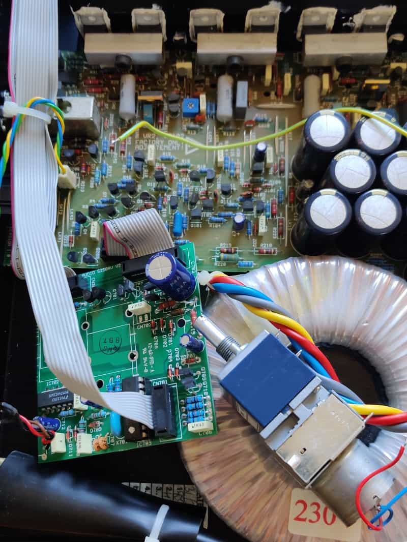
Creek 5250 SE
cored
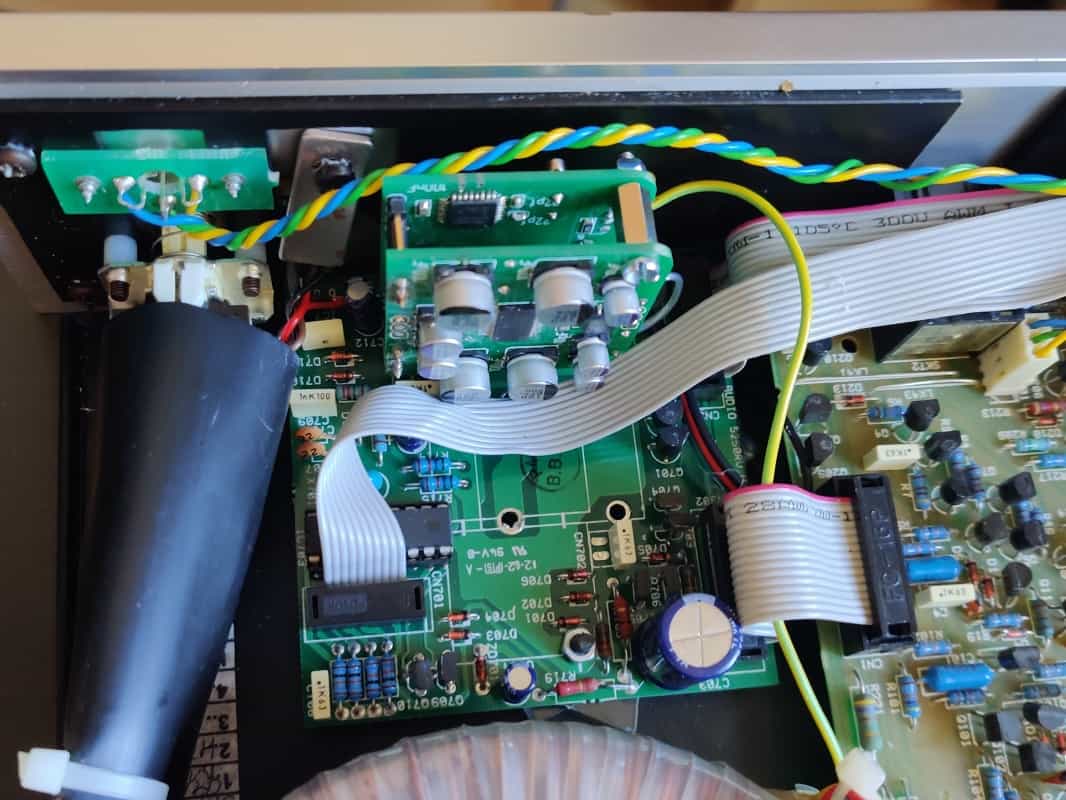
Uli's amplifier, a Creek, must be used as an object of desire. A motor-poti of the company Alps was installed here before. Normally I would have said, there I can easily get my board under. But the amplifier is really very narrow built up. I've already mentioned it. So I'm glad I banned the encoder to the edge. A first test shows me, that there is still not enough room. Fortunately the board holders are very high. I replace the 15mm holders with two 5mm high acrylic glass plates. Now it fits, but you have to be pretty clever to make our SAP run smoothly. to be installed.
Now we still need a place for the IR receiver. The Creek can be remote controlled as standard, so that an opening in the front panel is available. This opening is conveniently located in the immediate vicinity of the SAP, so that I can solder the IR_receiver directly to the circuit board and bend it so that it reaches into the opening. The original receiver must also be preserved. Fortunately the components fit next to each other in the front panel. I will test later if the reception works properly.
See-through
Now we still need a little electricity. The layout of the power supply board does not look very promising. Excitingly I find immediately +/-47V. Unfortunately a bit too much. But there should be a power supply on the potentiometer board of the Creek as well. Nevertheless I don't have much hope of finding a symmetrical tension. If necessary I have to add a small power supply board.
Surprise, the first two measuring points reveal to me a symmetrical voltage of more than 40V. Unfortunately still something too high. I decide to lower the voltage with a load resistor in series. So first of all measure the current consumption and calculate the resistances. The current consumption on the positive side is approx. 32mA, on the negative side slightly more than 8mA. After the connection has been established with two suitable resistors, I notice that the supply voltage has dropped significantly under the load. Positive I have after the voltage regulator now only 13V is available. So quickly dismantle everything again. Good that the hot glue used is still warm. After the recalculation I have a wonderful power supply and the potentiometer expresses its operational readiness by temporarily illuminating the Housing in yellow or green (LED).
Signals
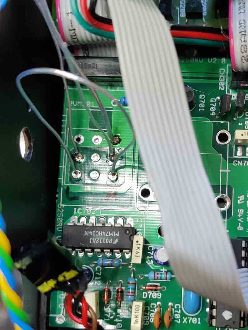
teflon-insulated silver wire
Not even three hours have passed (I hope the dripping irony of these words does not pass you by unnoticed) and I ONLY need to solder the signal lines. Okay, teflon-insulated silver wire will serve me well here. I solder the appropriate cables on the circuit board of the amplifier. I have disconnected the potentiometer and the side with the encoder is already inserted into the opening. Now I solder the cables to the board with the Muses chip, plug this on the other board and screw the stud bolt tight. Now screw the encoder in the front and everything should work.
Apart from the fact that a signal cable was not soldered in correctly and I later assembled the device without IR transmitter had been positioned correctly (the reception still worked), everything went smoothly. However it was already a time consuming work, as space was very limited.
Resume:
The potentiometer works perfectly. There is no crackling, distortions or similar disturbances. Of course I already had this with the oscilloscope. All functions can be easily adjusted. A real advantage is the possibility to set a certain volume increase (level). In my opinion the 223 steps are not really practical. The sound of the device is pronounced Sure. Of course, I can't really judge a sound impression, because I hadn't heard the Creek before the conversion. Honestly, I have to admit that the Creek is already playing at a pretty high level.
ready with soldering
Completely installed
back in great form
Updates
Later I reprogrammed the muting function a little bit. The potentiometer is not immediately set to "silent" or "music on". The The volume is now increased or decreased in small steps. A soft mute, so to speak.
The new boards, which are only 35x35mm in size, are ready. This makes the subsequent installation easier. This version already has a pin header to connect an RGB-Oled display (1.5 inch). The visualization makes it easier to add a balance control. The potentiometer can still be used without the display. Only the software is then different.
PCB in 35x35mm
7pin male connector
for RGB-Oled
Rotary Encoder
at the edge
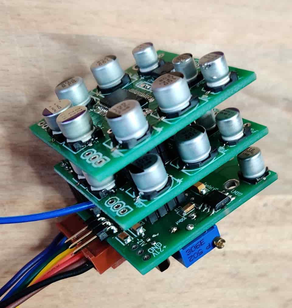
Muses 72320
cascadable
Since there were several inquiries regarding the XLR suitability of the chip, I made sure that the SPI and voltage connections were duplicated on the new boards. This allows another Muses board to be plugged in and controlled. The control also works perfectly if two Muses chips are addressed by the same address. A balance control is then not possible. But this is not usual in the high-end sector anyway.
Update from 31.08.2020: Today I ordered a board with a changed address. This board can be cascaded with the existing boards. This also makes balance control possible with the XLR version.
Update v. 18.01.2021: The software has been revised. Pressing the encoder button to call up the settings now leads to the the LEDs light up immediately. When the button is released, you got the corresponding menu. This is now already displayed while the button is pressed.
- yellow LED lights up - mute on/off
- green LED lights up - programming the remote control function
- yellow LED on (again) - programming current volume as power on volume
- yellow and green LED light up at the same time - programming the step of the volume increase
Muses-Boards
intertwined
XLR Poti complete
with Oled connector
Backside
Connector view
Since the software for the potentiometer with display differs significantly from the other software, we will go here to the project page: Muses-SAP with display
Our Muses 72320 can indeed do a little more than just make it louder or quieter.
The sensitivity can be increased to 0.25dB per step. Additionally, the control range can be changed to 0 to +31.5dB. The chip also allows a channel-separated volume control. This allows to easily add a balance function.
From my point of view it is problematic to realize these functions without visualization. Since it was my intention to use this chip in a preamplifier module, I am terminating this project at this point and links to the related page
Click here for the project page: PreAmp Module
Downloads